
|
Schematics tab > Devices group > Symbols |
Schematics tab > Markings group >  Cable menu > Save user cable marking Cable menu > Save user cable marking |
|
| Schematics tab > Markings group > Cable menu > User cable markings |
With these functions, you can create and insert your own cable marking symbols.
In addition to the Symbols window, marking symbols can be selected in marking functions (such as Add object information)
Do the following:
-
Start the function in one of the following ways:
-
In the Symbols window, select the
 (User's symbols) tab, click the arrow next to the
  (Save user symbol) button and select Save user marking symbol > Cable marking.
 -
On the ribbon, select the Schematics tab > Markings group >
Cable menu > Save user cable marking
-
-
Select objects to include in the symbol to be saved and press Enter.
-
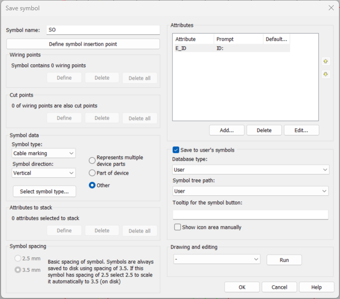
Indicate symbol's insertion point. The Save symbol dialog opens.
-
Define the following:
- Symbol name – Enter the name for the symbol to be saved. The function adds SO by default but you can name the symbols any way you want.
- Define symbol insertion point – Click to define the insertion point.
- Wiring points – In this section, you can see the number of wiring points in the symbol. Symbols have to include one or more wiring points i.e. points where the wire or cable can be connected (like a real terminal of equipment). Therefore, it is important to draw all lines (wires or cables) from one wiring point to another.
-
Define – First, indicate the wiring point to which you want to draw the wiring. The point is marked with a cross. Second, pick wiring point's number attribute i.e. the attribute from which to read the connection information.
-
Delete – Pick the wiring point you want to remove. Removing a wiring point also removes cut points associated with it.
-
Delete all – Delete all wiring points defined for the symbol.
- Cut points – In this section, you can see the number of cut points in the symbol. Two cut points make a pair, which can be used to cut line when inserting the symbol into the drawing.
-
Define:
-
Select 1. wiring point, which defines a cutting line: Select 1. wiring point (=cross) from the wiring point pair
-
Select 2. wiring point, which defines a cutting line: Select 2. wiring point (=cross) from the wiring point pair.
-
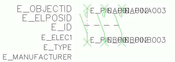
Function asks to select the next wiring point pair and marks the 1. wiring point pair with red dashed line.
-
-
Delete – Pick pair of cut points you want to remove. Cut points are marked with cross and dashed line.
-
Delete all – Removes all cut points from symbols wiring points.
- Symbol
data
-
The default symbol type is Cable marking.
-
By default, the symbol will be vertical.
- With Select symbol type, you can select several subtypes.
- Specify the symbol type by selecting Represents multiple device parts, Part of device or Other.
-
- Attributes to stack – Select this if you want to select attributes that are allowed to stack. It means that if attribute value is empty, another attribute can take its place, thus eliminating gaps between attributes. Pick the attribute definition to add for the stacked attributes by clicking Define.
- Attributes – You can add, delete and edit the attributes.
-
Add – Select the desired attribute and insert default value if needed. Click OK and indicate the insertion point.
-
Delete – Remove an attribute.
-
Edit – Edit attribute properties. You can edit the order of attributes in the symbol with the arrow buttons.
- Save to user's symbols – If you want the symbol to be available in the Symbols window, select this. Otherwise, the symbol will be saved to the symbols in your user profile but it will not be shown in the Symbols window.
- Database type – Select the type of the database: User or Shared.
- Symbol tree path – Select the desired symbol tree folder from the drop-down menu, or create a new one by selecting New. The folders can be managed in the Symbols window.
- Tooltip for the symbol – Define the tooltip shown when hovering over the symbol.
- Show icon area manually – Outline the area you want to show in the symbol icon.
- Drawing and editing – Select the desired edit function (such as Draw line) from the drop-down menu and click Run. When the action is completed, the function will return back to the symbol saving dialog automatically.
 Show/hide details
Show/hide details
Show/hide details
-
Click OK.
You can insert your own cable marking symbols by selecting the Schematics tab > Markings group > Cable menu > User cable markings.