Save your own symbols

|
Single-line tab > Devices group > Symbols |
On the  (User's symbols) tab in the Symbols window, you can create your own
Important: The symbol functions of CADMATIC Draw should not be used with symbols related to the Electrical application.
Do the following:
-
In the Symbols window, select the
(User's symbols) tab. -
Click the
 (Save user symbol) button.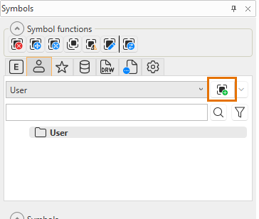
-
Select objects to include in the symbol to be saved.
-
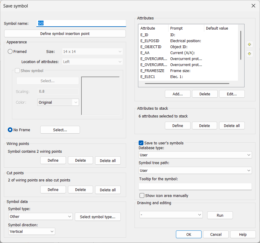
Indicate symbol's insertion point. The Save symbol dialog opens.
-
Define symbol information:
- Symbol name – Enter the name for the symbol to be saved. The function adds SO by default but you can name the symbols any way you want.
- Define symbol insertion point – Click to define the insertion point.
- Appearance – The appearance can be framed or not framed. By default, the appearance is set to No Frame.
- Framed – The objects you selected after starting the function are added to the framed symbol.
There is a wiring point in the middle of each side of the frame. The top and bottom wiring points form a cut point pair, as well as the left and right wiring points.
The highest wiring point is the insertion point.
You can insert attributes inside the frame, to the right or left of the symbol, or above or below the symbol. Default attributes are located automatically. ID attributes are stacked automatically.
If you select Show symbol, you will see a preview of the symbol you selected after starting the function. In addition, with the Select button you can replace the objects with those you select from the drawing or in the Symbol selection dialog (see Symbol selection).
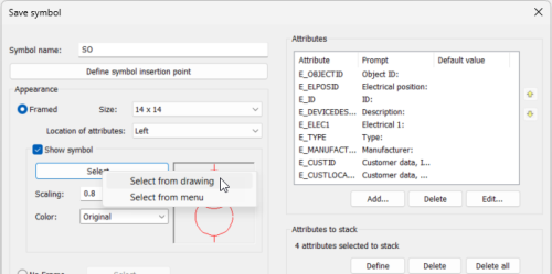
The objects you selected after starting the function are then removed, and the newly selected is added inside the frame.
In the Symbol selection dialog, the symbols are by default shown based on the drawing type but you can also select the Arrangement drawing type from the Electrical symbols drop-down menu.
- No Frame – With Select, you can replace the selected objects with those you select from the drawing or in the Symbol selection dialog (see Symbol selection). In the Symbol selection dialog, the symbols are by default shown based on the drawing type but you can also select the Arrangement drawing type from the Electrical symbols drop-down menu. The objects you selected after starting the function are removed.
- Framed – The objects you selected after starting the function are added to the framed symbol.
- Wiring points –
-
Define – First, indicate the wiring point to which you want to draw the wiring. The point is marked with a cross. Second, pick wiring point's number attribute i.e. the attribute from which to read the connection information.
-
Delete – Pick the wiring point you want to remove. Removing a wiring point also removes cut points associated with it.
-
Delete all – Delete all wiring points defined for the symbol.
- Cut points – In this section, you can see the number of cut points in the symbol. Two cut points make a pair, which can be used to cut line when inserting the symbol into the drawing.
-
Define:
-
Select the 1st wiring point for the wiring point pair.
-
Select the 2nd wiring point for the wiring point pair. The first wiring point pair is marked with a red dashed line.
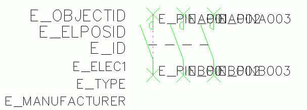
-
Select the next wiring point pair.
-
-
Delete – Pick pair of cut points you want to remove. Cut points are marked with cross and dashed line.
-
Delete all – Removes all cut points from symbols wiring points.
- Symbol
data
- Symbol type is important for the functions to recognize the symbol to certain electric symbol.
-
The default symbol type is Other, and the default subtype Single-line Diagram Symbol.
-
If you selected a symbol, the symbol type is set accordingly and Single-line Diagram Symbol will be set as the subtype.
-
Symbol type is not included in the E_ID attribute.
- Select to create a horizontal or vertical symbol.
- With Select symbol type, you can select several subtypes.
-
Attributes – E_ID (ID) is required.
You can add, delete and edit the attributes.
-
Add – Select the desired attribute and insert default value if needed. Click OK and indicate the insertion point.
-
Delete – Remove an attribute.
-
Edit – Edit attribute properties. You can edit the order of attributes in the symbol with the arrow buttons. See Edit attribute properties.
- Attributes to stack – If the attribute value is empty, another attribute can take its place, thus eliminating gaps between attributes. Define attributes that are allowed to stack by clicking Define, then pick the attribute definition to add for the stacked attributes.
- Save to user's symbols – If you want the symbol to be available in the Symbols window, select this. Otherwise, the symbol will be saved to the symbols in your user profile but it will not be shown in the Symbols window.
- Database type – Select the type of the database: User or Shared.
- Symbol tree path – Select the desired symbol tree folder from the drop-down menu, or create a new one by selecting New. The folders can be managed in the Symbols window.
- Tooltip for the symbol – Define the tooltip shown when hovering over the symbol.
- Show icon area manually – Outline the area you want to show in the symbol icon.
- Drawing and editing – Select the desired edit function (such as Draw line) from the drop-down menu and click Run. When the action is completed, the function will return back to the symbol saving dialog automatically.
 Show/hide details
Show/hide details
Show/hide details
-
Click OK.
Edit attribute properties
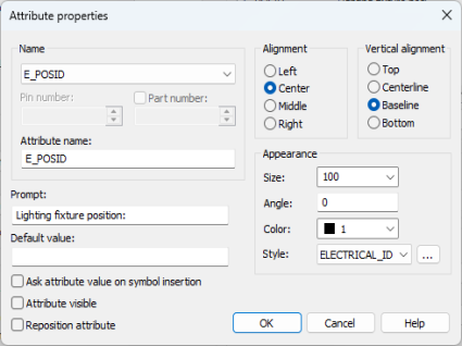
In the Save symbol dialog, click Edit to open the Attribute properties dialog.
-
Pin number – Define the running number for pin attributes.
-
Part number – Compiled symbols require a part number. If different symbols are used for different device occurrences and the symbols have the same attributes while they mean different things, you have to define a part number, which separates the pins from each other.
An example of a compiled contactor symbol
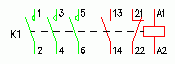
E_PINA001[112], Value: 1, Part number: 112
E_PINB001[112], Value: 2, Part number: 112
E_PINA001[114], Value: 3, Part number: 114
E_PINB001[114], Value: 4, Part number: 114
E_PINA001[116], Value: 5, Part number: 116
E_PINB001[116], Value: 6, Part number: 116
E_PINA001[202], Value: 13, Part number: 202
E_PINB001[202], Value: 14, Part number: 202
E_PINA001[201], Value: 21, Part number: 201
E_PINB001[201], Value: 22, Part number: 201
E_PINA001[101], Value: A1, Part number: 101
E_PINB001[101], Value: A2, Part number: 101
-
Attribute name – The name is generated from the attribute, pin number and part number.
-
Prompt – Define the prompt/description shown when using the symbol.
-
Default value – Define a default value for the attribute. Alternatively, you can leave this blank and select to define the attribute value on symbol insertion.
-
Ask attribute value on symbol insertion – Select this if you want the application to ask for the attribute value when you insert the symbol. If you defined the default value, that will be used.
-
Attribute visible – Select this if you want the attribute to be shown in the drawing.
-
Reposition attribute (available when editing) – Select this if you want to reposition the attribute you are editing.
-
Alignment and Vertical alignment – Define the horizontal and vertical alignment for the attribute.
-
Appearance – Define the size, angle (in degrees) and color of the attribute.
-
Angle – The angle is typically 0, for vertically readable attributes 90 or 270. Other free angles are also supported.
-
Style – Select the desired text style by clicking the
 button.
-