|
|
Electrical tab > Documents group > New |
With this function, you can open the Start a new Electrical drawing dialog and start creating a new drawing. When creating a new drawing with this function, you can be sure that all the necessary settings are correct. Furthermore, when you open a drawing with drawing type defined, the correct ribbon tab with suitable functions and symbols will automatically open. Also see Set drawing types.
Do the following:
-
Define the drawing type.

-
Single-line diagram – For creating any kind of single-line documents such as key single-line, distribution single-line, and block diagrams.
-
Load diagram – For creating horizontal and vertical load diagrams presenting feeders of one distribution board by using feeder symbol packages defined in feeder properties
-
Distribution board (table) – A special type to be used only with the old Distribution board table style where graphical feeder package symbols are combined to a table
-
Arrangement – For creating arrangement documents with real measurements in the model space. Distances can be measured from the documents, and the X, Y and Z coordinates are saved to the Electrical database.
-
Arrangement (not in scale) – For creating arrangement documents without any measurements, such as cable length
-
Multi-line diagram – For all kinds of schematics and multi-line style documents utilizing the sheet method: in the same drawing file, the different sheets are located on different layers
-
Cabinet layout – For cabinet layouts drawn with real measurement in the model space.
-
Table – An Electrical document type for old table forms. Functions related to this drawing type are located on the Electrical tab, so you need to activate another toolset by selecting a drawing, which has a drawing type set.
-
Other – For handling basic CAD documents done with another software, mostly using basic CAD functions.
If necessary, you can click Skip to close the dialog without defining the initial information. The drawing type or other configurations will not be saved to the drawing.
-
-
If necessary, click the
 button to define a new project directory. If directory memory is in use, the last directory used is shown by default.
 -
Enter a new name for the drawing.
-
If you want to prevent the drawing creation function from opening automatically, remove the selection from Show this dialog when starting a new drawing. By default, the function always starts when you create a new drawing.
-
Click OK. What happens next depends on the drawing type you selected:
-
If you selected Cabinet layout, the Set sheet dialog opens.
 Show/hide details
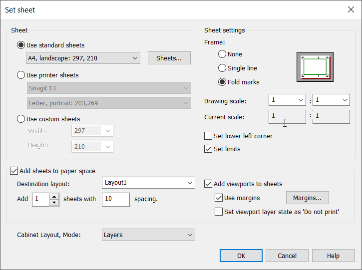
Define the settings:
-
Select the sheet size:
-
Use standard sheets – Select the size to use from the list. You can add, delete and edit sheet sizes by clicking Sheets. These sizes are stored to a text file Arkit.lue (in application folder).
-
Use printer sheets – Select the desired printer and printer's paper size. The list of papers depends on the printer / print configuration.
-
Use custom sheets – Select sheet width and height from the drop-down menu, or enter the desired values into the fields.
-
-
Define sheet settings:
-
Frame – Select to draw the frame either with a single line or fold marks, or not at all.
-
Drawing scale – Select the drawing scale from the list, or enter values into the fields.
-
Set lower left corner – Select this if you want to enter the lower left corner of the sheet.
-
Set limits – Select this if you want to set the drawing limits according to the paper size. This function is disabled in print mode.
-
-
If you want to create drawing frames to print mode and print mode viewports, selectAdd sheets to paper space. No frame will then be drawn to design mode. Frames and viewports are created side by side according to the gaps you define.
Also define the following:
-
Select the layout to which the sheet is created. Alternatively, enter a new layout name to create a layout by that name.
-
Define the number of frames and the gap between the frames.
-
If you want to create a layout viewport to the frame you are about to draw, select Add viewports to sheets. You can also define margins for the viewport and set Do not print as the layer state.
By default, the frame will be drawn to a layer named FRAME and viewports to a layer named VIEWPORTS. If you are using some toolset, the function will fetch the correct layer from that toolset.
-
-
If necessary, select the drawing mode to use from the Cabinet Layout, Mode drop-down menu:
-
Layers – Objects (doors, mounting plates, etc.) are drawn on top of each other at different layers.
-
Sheets – Objects are drawn side by side to the active SLEHTI layer.
The function remembers your selection, and uses it by default the next time.
-
-
-
If you selected Arrangement or Arrangement (not in scale), the New Layout Drawing dialog opens.
Show/hide details
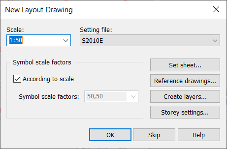
Define the settings:
-
Scale – This function is used to set the scale in the drawing and to set the dimension scale factor of the dimension styles in the drawing to the same value. The dimension scale factors should be changed only if the dimension scale factor is the same as the scale before the change.
-
Setting file – This function is used to select the desired setting file for use. After this selection, the positioned symbols, wirings, etc. are given layers, colors, etc. according to the selected setting file.
Note: Change of the setting file does not affect the existing symbols and wirings in the drawing. If the existing items in the drawing should be converted according to new setting file, function Convert drawing according to the setting file should be used.
-
Symbol scale factors – Many of the Layout application symbols are scalable. This menu is used to set symbol scale factors to the drawing, so that the inserted symbols will be scaled according to the selected factor in X and Y direction. Symbol scale factors are often set according to the printing scale.
Note: Changing this setting does not affect symbols already in the drawing.
Note: The symbol scale factors have no effect on symbols, whose size is fixed or defined by the user (e.g. linear light fixtures).
-
Create layers – This function can be used, if you want to create some layers to drawing for future reference.
-
-
-
Click OK.
-
If you selected Table or Other as the drawing type, the Electrical tab stays open. Otherwise, the tab related to the selected drawing type opens.
-
The drawing frame is automatically inserted for single-line diagrams, load diagrams, multi-line diagrams, and cabinet layouts. If default frames have been set in the project settings, those are inserted. If default frames have not been set, the frame is set according to the Drawing frames and logos dialog.
-