|
|
With this function, you can draw various types of cableways, cable trays, contact rails, wire ducts, busbars, pipes, etc. You can change most values while drawing and editing in the Cableway dialog that opens when you start to draw or edit. The changes are applied immediately.
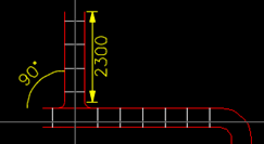
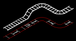
The cableways can be drawn in different viewing directions; traditionally in the 2D top view or in the 3D view as in the sample drawings. The angle is determined based on the picked direction and tolerance of angle defined in the settings. The tolerance tries to round off the picked angle to the nearest 45-degree angle.
While drawing, ascending/descending cableways are done by selecting a new elevation in the drop-down menu. The previous picked point remains at the previous elevation and the next picked point gets a new elevation value. A cableway is drawn between these at the angle given in the pitch angle setting. If a free angle is used, the angle of the cableway is determined based on the elevation difference and distance. The cableways to another floor, where the cableway continues, can be done by selecting the floor in the floor drop-down menu. The symbol of the vertical cableway is added to the cableway point, and drawing continues on the selected floor. The vertical cableway can be done by pressing the Tab key. Then the next cableway section is a vertical cableway upwards or downwards. Cableway 3D or 2D/3D geometry must be selected and view must be selected from an angle so that the cableway direction can be pointed.
Do the following:
-
Select the cableway type: cable tray, contact rail, trunking, power busbar, suspension rail, pipe, or other if nothing else fits.
You can save the cableway settings for later use when drawing a new cableway or editing an existing cableway. For more information, see Save the settings.
-
Select a type for the cableway from the product database, or enter it manually. The types existing in the drawing are shown in the drop-down menu. You can add new product information by clicking the
 button.
If the selected cableway type comes from the product database,
the button icon turns into a database icon:
button.
If the selected cableway type comes from the product database,
the button icon turns into a database icon: 
-
Define the system. The System drop-down menu contains the cableway systems used in the drawing. You can also pick the system from an element in the drawing with the
 button. With Add, you can open the system
selection dialog and select from all the systems available.
button. With Add, you can open the system
selection dialog and select from all the systems available. Show/hide details
When you select a function, the System selection dialog opens and you can select the desired system either from all the available systems or your own systems. The function saves your criteria after selecting the system, so all the criteria you define in this dialog will be used by default the next time the System selection dialog opens.
Options of the selection list can be filtered in this window. Filtering is performed by choosing at least one of the following options: Power current systems, Weak current systems, and Other systems. In addition to these, the desired system layers should be selected among the following: Components, Markings, Wirings, Wiring markings and 3D-systems. In addition, you can enter search criteria in the Filter field. The filtered data can be organized according to the desired column by clicking the column header.
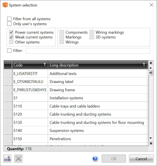
It is also possible to define a user filtering mask. The mask may contain wildcard characters * and ?. Several user filtering masks, separated with commas, can be defined at the same time. The user defined mask is not implemented, until all other filtering tasks have been performed. When the option Filter from all system is selected, filtering is performed from all existing systems in addition to systems defined in the function command string. The user defined systems can be displayed with the option Other systems.
With the Pick button, the system data can be copied from the element indicated in the drawing.
-
Define the size and location information:
-
Width/Depth – Width of the cableway, e.g., of a cable tray.
-
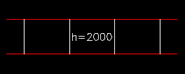
Height – Height of the cableway from bottom to top.
-
Elevation – The elevation position of the cableway. The elevation can be picked from the selected element with the elevation pick tool by clicking the
 button. Select in the lower drop-down menu
which point of the cableway is set at the chosen elevation: lower edge, centerline
or upper edge.
button. Select in the lower drop-down menu
which point of the cableway is set at the chosen elevation: lower edge, centerline
or upper edge. -
Rise angle – The angle for the cableway if a new elevation is selected while drawing.
-
Storeys – If the project includes several floors and floor settings are set, you can select another floor where the wire route continues while drawing. A cableway symbol is placed at the cableway point, you move to another floor and continue drawing the cableway on the chosen floor.
-
Installation method – Additional information about the installation method of the cableway, for example mounting method, material, etc.
-
-
Define the drawing line i.e. the location where the cableway is drawn relative to the indicated line. When drawing according to the edge line, it is possible to define the distance to the line to be drawn. This is practical when drawing a cableway next to a wall at the installation clearance, and then you can make the selection directly according to the wall.
-
Define the geometry settings:
-
2D, 3D or 2D/3D – You can draw the cableway in 2D, 3D or so that both 2D and 3D cableways are drawn simultaneously.
-
Pattern – Select the presentation type for the 2D cableway to be drawn.
-
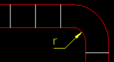
Corners – Select the corner type for the cableway:

= rectangle 
= curved corners 
= curved corners and pitches -
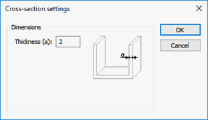
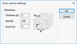
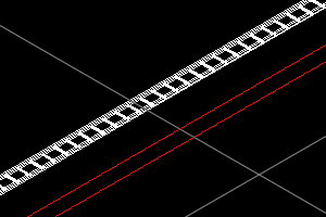
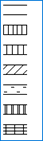
Cross-section – Defines the cross-section of the 3D cableway.

= Rectangle = Ladder tray = Plate tray = Wire mesh tray Dimensions of the cross-section can be edited with the
button for each cross-section, except for the rectangle,
which is drawn according to the width and height of the cable
tray.Show/hide images
Ladder tray:

Plate tray:
Wire mesh tray:
-
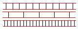
Sparse/dense – A sparse or dense drawing mode. If neither is checked, then the normal drawing style is used.
-
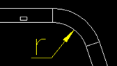
Inner radius – When using curved corners, this setting defines the inner radius (r) of the curve.
-
Vertical part – This setting defines the presentation style of the vertical cableway:

-
Rotation – This defines the installation direction of the cableway, for example the cableway can be drawn vertical when installing it on a wall.
-
Settings – Includes additional settings associated with drawing a cableway.
Show/hide details
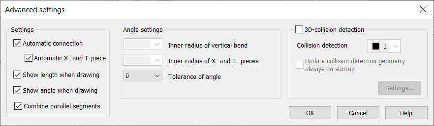
Automatic connection – If a cableway is drawn to connect to another cableway, they are connected automatically. Setting can be toggled temporarily by holding Alt Gr key.
Automatic X- and T-pieces – Also T- and X -piece branches are made automatically in the above mentioned situation.
Show length / angle when drawing – Shows length and angle dimensions of the cableway while drawing.
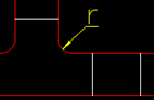
Inner radius of vertical corner – Fillet radius (r) if using filleted corners in cableways as well.
Inner radius of T- and X-pieces – Fillet radius (r) for connecting cableway branch pieces to each other when using filleted corners.
Combine parallel segments – Setting determines if two cableway parts are combined into one if they are perpendicular to each other and they have same endpoint.
Tolerance of angle – The tolerance for rounding off the angle to the nearest 45-degree angle while drawing.
3D collision review – The collision review helps detect any collisions against another structure while drawing the cableway. The colliding cableway is highlighted with a collision color.
-
Free text / Elevation – You can insert desired text over the cableway by selecting either Free text or Elevation.
- Free text selection allows typing the text in the drop-down menu or selecting any text that has been used earlier.
-
Elevation selection marks the cableway's elevation at drawing point automatically over the cableway:
-
Draw caps – With this option, end lines will be added to both ends of the cableways.
Show/hide images
Option enabled Option disabled 
Show/hide image
At the top normal, then sparse and finally dense:

-
-
Start drawing the cableway by indicating the start and end points for the cableway in the drawing. The final location of the cableway is determined by the size and location information and the drawing line.
-
Click on the next cableway, end or angle point of the cableway. If you want to complete the draw, press Enter or accept the input with the right mouse button. If you want to continue drawing, pick the next point.

Save the settings
You can save the cableway settings and then use them later when drawing a new cableway or editing an existing cableway.
Do the following:
-
Click the
button next to the Saved settings field. The Saved settings dialog opens.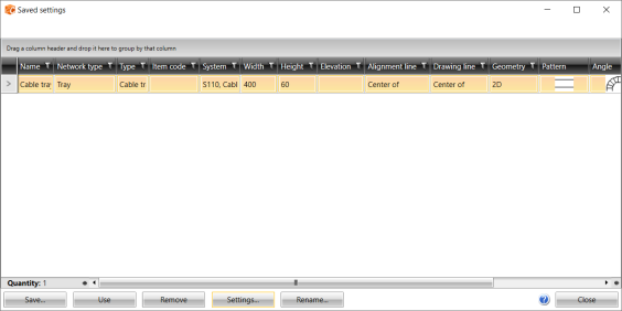
-
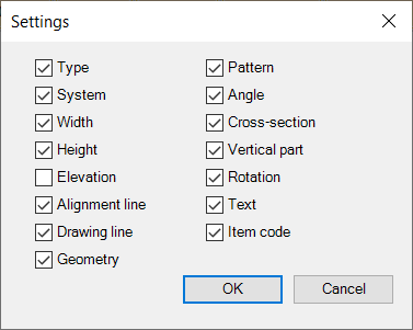
Click Settings, and select which information from the Cableway window is saved. Changing the settings does not apply to the previously saved information.
-
Click Save.
You can take the selected settings into use by selecting the desired row and clicking Use.
If necessary, you can rename settings or remove them:
-
Remove – Remove the selected settings from the list.
-
Rename – Rename the selected settings.