Create an Electrical drawing
Let's create a new Electrical drawing, and attach the floor plan we previously saved as a reference drawing.
It is important to draw arrangements in real scale in the design mode. In addition, the print scale is needed, as well as the symbol scale factors in order to have the symbols in the desired size.
These settings make drawing easier, in addition to which they affect the final outcome – the drawing creation function goes through the settings systematically. By default, this function is activated when you start a new drawing.
Do the following:
-
Select Electrical tab > Documents group > New. The program opens a new document tab, and the Start a new Electrical drawing dialog opens.
-
Define the following:
-
As the drawing type, select Arrangement below Layout.
-
For the project directory, select [CADMATIC directory]\Samples\Electrical\Layout exercise.
-
For the drawing name, enter ELEC_2100.drw.
-
-
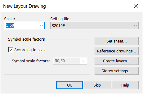
Click OK. The New Layout Drawing dialog opens.
-
Define the following:
-
For scale, select 1:50.
-
Select a setting file.
-
Set the symbol scale factors according to scale.
-
-
Attach the previous floor plan as a reference drawing as follows:
-
Click Reference drawings.
-
Navigate to [CADMATIC directory]\Samples\Electrical\Layout exercise\REF.
-
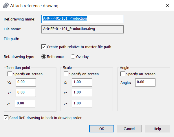
Double-click the A-0-FP-01-101_Production.dwg file. The Attach reference drawing dialog opens.
-
In the Ref. drawing name field, enter Floor plan 1st floor as the description. This will not affect the file name.
-
Select Create path relative to master file path. The relative reference drawing will be shown for everyone handling the master drawing, as long as they have the reference drawing and it has been saved to the same directory as the master drawing. The reference drawing type is an absolute directory location so it might not show correctly for everyone.
-
If you do not want the reference drawing attached to the reference drawing to be shown, select Overlay.
-
Accept the default settings for the reference drawing by clicking OK. The program attaches the floor plan as a reference drawing to the new drawing.
You can also add reference drawings via the Reference drawing window
-
-
Click OK. Check that the Layout tab is active (underlined). If some other application is active, change it from the Start Page. If the application was wrong, you also need to change the drawing type: Select Electrical tab > Documents group > Drawing type and then Arrangement below Layout.
Before moving on, create another drawing file by the name of ELEC_2200.drw and add A-0-FP-01-201_Production.dwg as the reference drawing as described. The reference drawing is in the same directory as the first floor reference drawing.
 Previous Previous |
Next

|