Draw device boundaries
Next, we will create device boundaries (=123-Q10 and =123-M01) with which you can define drawing elements for specific devices.
Tip: The ID for the bounded area can be added to the drawing as one text or three separate texts (objet ID, electrical position, and device ID). In addition, you can locate the text either inside or outside the bounded area. The bounded area can include all kinds of elements.
Do the following:
-
Select Schematics tab > Other functions group > Boundaries menu > Device boundary. The Device boundary dialog opens.
-
Define the following:
-
Object ID – =123
-
ID – Q10; with the
 (Browse) button, you can easily select the device from the project tree:
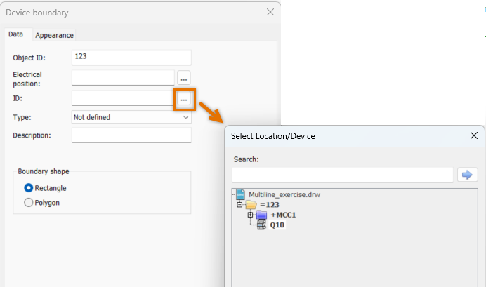
-
-
Indicate the first corner of the bounded area.
-
Indicate the second corner of the bounded area.
-
Create device boundaries for =123-M01 as described.
Note: If you need to edit the bounded area (the size or the shape) later, select it, right-click and select Redefine bounding area.
 Previous Previous |
Next

|