Annotate tab > Dimensions group > ![]() (Dimension style), DIMSTYLE
(Dimension style), DIMSTYLE
Dimension styles could be seen as a collection of dimension settings. Assigning a particular dimension style to a dimension object forces it to adopt all the dimension settings defined in the style.
In every drawing there is at least one dimension style named STANDARD. Other styles have to be created by the user. If you import drawing from other system in DXF or DWG format, their dimension styles will also work in CADMATIC.
If you want to be sure that all dimensions in the drawing follow the dimension style settings (without editing the dimension style), do the following:
-
Enter the DIMUPDATE command.
-
Select dimensions to update.
-
Confirm selection by pressing Enter.
Create dimension styles
You can create and edit dimension style with the DIMSTYLE command. If you then save a new dimension style with the Save function, the new dimension style will adopt all the current dimension settings.
Alternatively, create dimension styles via the Dimension style dialog.
Do the following:
-
Select the Annotate tab and in the Dimensions group click the
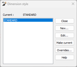
 (Dimension style) button. The Dimension style dialog opens.
-
Click New.
-
Enter the name of the new dimension style, and click OK. The dimension settings open.
-
Define the desired settings to the dimension style and click OK.
-
If you want the set the new dimension style as the current style, select Make current.
-
Click OK. If you selected Make current, e program will prompt for a confirmation, that you really want to make the new style the current style.
Edit dimension style settings
Dimension style manages the numerous settings of dimensions. Dimension style is a set of dimension settings which dimensions in drawing use.
When you edit an existing dimension style, the changes will automatically apply to new dimension objects that use the edited dimension style. When you edit a dimension style, all dimensions using that style in the drawing are regenerated.
Do the following:
-
Select the Annotate tab, and in the Dimensions group click the
 (Dimension style) button. The Dimension style dialog opens.
 -
Select the style you want to edit.
-
Click Edit. The settings open. The dialog also includes a preview window which shows what a dimension will look like using the current dimension style.
-
On the Lines tab, define the dimension line settings:
-
Color – Color of the dimension lines and arrowheads. If you select the color SYMBOL, the color of the dimension can be changed later in the drawing. If selected color is i.e. red, the dimensions will always be generated with red color and the color be changed later.
-
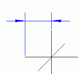
Line extension – Dimension line extension over the extension lines (applies only when arrowheads are set to Line).
-
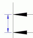
Line spacing – Spacing between separate dimension lines in baseline dimensions. Actual spacing is the set value multiplied by the dimension text height. For example, dimension text height is 3.5 and dimension line spacing is set to 2.5, the actual spacing will be 8.75.
-
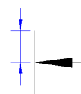
Extension line extension – Extension line extension over the dimension lines.
-
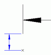
Extension line offset – Extension line offset from the dimension points.
-
Select whether to draw the dimension lines and dimension extension lines. This setting can be set separately for the first and the second line.
-
-
Define the arrowheads:
-
Select the Arrowheads tab.
-
Define the settings:
-
First, Second and Leader – Select a symbol from the list to use as arrowhead. You can also select any symbol in the drawing to use as arrowhead by selecting Select symbol from drawing.
-
Arrow size – The size of arrowheads in dimensions and leaders.
-
Scale factor – Factor with which all dimension components, such as dimension text and arrowheads, are multiplied with. This value is often set to same value as drawing scale.
-
Centermark size – Centermark size in radial and diameter dimensions. If 0, no centermark is displayed.
-
-
-
Define the text:
-
Select the Text tab.
-
Define the settings:
-
Color – Dimension text color.
-
Style – Text style of the dimension text. This applies i.e. to dimension texts and tolerance texts.
-
Size – Dimension text height.
-
Unit – A string to be added to the dimension value. For example, setting unit to mm will display mm at the end of all dimension values.
-
Scale factor – Factor that dimension value is multiplied with. I.e. if scale factor is 2 then dimension texts show a double value.
-
Gap – Gap between tolerance frame and tolerance text.
-
Diameter symbol – If selected, a diameter symbol is added to all dimension texts.
-
Draw frame – If this is selected a text sized rectangle will be drawn around the dimension text.
-
Text placement – Dimension text can be set to vertically on the dimension line or above the dimension line. Horizontally text placement can be centered or set onto first or second dimension extension line. You can also define how to place text when text is moved (Dimension line moves with text / A leader is added / Normally).
Text can also be set to automatically generate horizontally if text is between or outside the dimension extension lines.
-
-
-
Define the units:
-
Select the Units tab.
-
Define the settings:
-
Angle unit – Units to use when creating a angle dimension. Choices are Degrees, Radians, Grads or Deg/Min/Sec.
-
Linear units – Units to use when creating a linear dimensions. Choices are Scientific, Decimal, Engineering, Architectural or Fractional.
-
Decimals and Angle decimals – Number of decimals used in dimension texts.
-
Round – Rounding value for dimension text (number):
-
0 – Round only to selected decimals
-
0.1 – Round to nearest tenth part (i.e. dimension value 14.467 => rounded value 14.5
-
1 – Round to nearest integer
-
10 – Round to nearest ten
-
-
-
-
Define the tolerances:
-
Select the Tolerances tab.
-
Select Tolerances so that the program will draw tolerance text to dimensions (using this dimension style). You can set tolerance symbol and lower and upper limit values in dimension style, but then every dimension using this style gets the same values. That is why generally tolerance values are attached to dimensions as dimension overrides.
-
Define the settings:
-
Tolerance symbol – A tolerance symbol to be added to all dimensions (for example H7).
-
Upper limit value – Global tolerance upper limit
-
Lower limit value – Global tolerance lower limit.
-
Decimals – Number of decimals in the global tolerances (default 3)
-
Scaling for height – Height factor for tolerances. If set to 1, tolerance texts are the same size as the dimension text. Tolerance text size = Height factor * Dimension text size.
-
-
-
Click OK.
