There are separate address creation rules for each I/O card manufacturer. The address is automatically created when you define the Start address IN or the Start address OUT information when creating I/O cards or editing them. You cannot edit addresses for individual channels when they have been automatically created.
The addresses are created with the following values:
{0} = Short card ID. If the full ID is =123+MCC1-A01-A1, the short one is A01-A1.
{1} = Short rack ID. If the full ID is =123+MCC1-A01, the short one is A01. If no rack has been defined for the card, empty.
{2} = Short rack ID. If the full ID is =123+MCC1-A01, the short one is A01. If no rack has been defined for the card, the value is Local.
{3} = Value from the card's Start address IN field.
{4} = Value from the card's Start address OUT field.
{5} = Value from the card's Station ID field.
{6} = Value from the card's Field controller field.
{7} = Value from the Station ID electrical position.
{8} = Value from the card's PIC-number field.
{9} = Value from the card's Type field (DI, DO, AI, AO).
{10} = Value from the channel's Channel number field.
{11} = Not used.
{12} = Value from the channel's Word change field.
{13} = Value from the channel's Bit address offset field.
{14} = Not used.
{15} = Value from the channel's Spare 1 field.
{16} = Value from the channel's Spare 2 field.
{17} = Value combined from the card's Start address IN and Word change fields.
{18} = Value combined from the card's Start address OUT and Word change fields.
{19} = Value combined from the channel's Start address IN and Word change or Start address OUT and Word change fields, depending on which start value you enter.
{20} = Value combined from the channel's Bit address and Bit address offset fields.
{21} = Value from the card's Card slot field.
{22} = Value from the channel's Channel number field -1.
{23} = Value from the card's Spare 1 field.
{24} = Value from the card's Spare 2 field.
{25} = Value from the channel's Card ID field without the rack ID, i.e. the sub-device ID. If the rack ID is A200-A10 and the card ID is A200-A10-AB-100, the value without the rack ID is AB-100.
Define the rule as follows:
-
From the Product models project tree, select Edit to open the I/O card product model for editing.
-
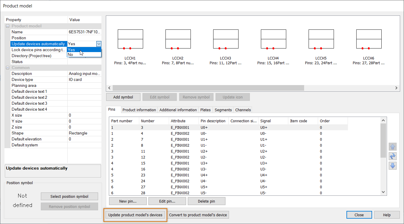
From Update devices automatically, select Yes. If you select No, you need to manually update the changes to the devices using the product model with the Update product model's devices button.

-
Select the Channels tab.
-
Double-click the desired channel. Alternatively, select the channel and click Edit channel. The Channel dialog opens.
-
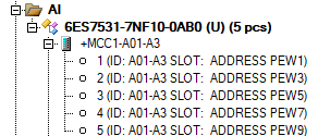
In the Address Prefix field, enter the desired format. For example, if you want to see the short card ID, the card slot and the address, enter ID: {0} SLOT: {21} ADDRESS PEW{17} (in which PEW is the AI card prefix).

-
Define the same format to other channels as follows:
-
Copy the format from the Address Prefix field.
-
Close the Channel dialog by clicking OK.
-
Double-click the next channel row, and paste the format to the Address Prefix field.
-
Close the Channel dialog by clicking OK.
-
-
Close the Product model dialog by clicking Close. The changes are updated to the project tree:

-
If necessary, update the missing information (such as the slot) to device properties. The changes are automatically updated to both the project tree and the drawing.
When you define the Start address IN and Start address OUT values, the program forms the addresses to the cards in the channels according to the rules.

