Visualization control

The Visualization Control toolbar button opens a menu for configuring the appearance of the 3D view.

Edges
-
No edges – Objects have no distinct edge lines. This is the fastest visualization mode and recommended for very large models.
-
Edges – Objects display feature edges (sharp edges and seams, such as welding joints).
Point clouds
-
Show point cloud scanner points – If selected, the point cloud scanner points are visible.
-
Points – Point clouds are visualized using points.
-
Splats – Point clouds are visualized using splats (slightly larger than points).
-
Show point cloud difference – Activates difference mode comparing the 3D model and the point cloud in visualization. The tool is not accurate and is only meant for visualization purposes. By default, the parts where the model and the point cloud differ less than the set tolerance value are highlighted with green. The parts found only in the point cloud are highlighted with red, and the parts found only in the 3D model are highlighted with blue. Grey areas are too far away from the camera and cannot be compared by visualization. The tolerance value and colors can be changed in Settings > Point clouds. See Point clouds.
Insulations
-
Hide insulations – Insulations are not visible.
-
Show transparent insulations – Insulations are transparent. Objects that are inside or behind the insulation are clearly visible.
-
Show semitransparent insulations – Insulations are semi-transparent. Objects that are inside or behind the insulation are at least partially visible.
-
Show opaque insulations – Insulations are completely rendered. Objects that are inside or behind the insulation cannot be seen.
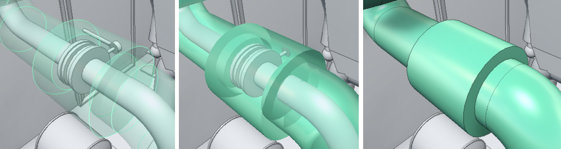
In this example, the left image displays transparent insulation, the middle image displays semitransparent insulation, and the right image displays opaque insulation:
Welds
-
Show welds – If selected, welds are visible.
Cable routing objects
-
Show cable routing objects – If selected, cable routing objects are visible.
Connection points
-
Show connection points – If selected and the model contains connection points, the connection points that are near the cursor are visualized. When in Examine Mode only the connection points of the examined object are shown. Moving the cursor over a connection points displays the node number.
Note: Snapping to connection points can be toggled on or off—see Measure.
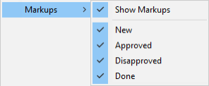
Markups
Select whether to show markups in the 3D view. If they are shown, you can select which statuses to display.
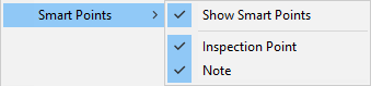
Smart Points
Select whether to show Smart Points in the 3D view and map. If they are shown, you can select which types to display.
Visual styles in legend
-
Show all visual styles in legend – If selected, the visual styles legend shows all visual styles. If not selected, only the visual styles of visible objects are shown.
Coordinates
-
Show coordinate display – If selected, the current camera coordinates are displayed at the bottom of the 3D view. By default it shows named coordinates, but if named coordinates are not available, Cartesian coordinates are shown instead.

-
Show coordinate marker – If selected, a main axis marker is displayed in the bottom-left corner of the 3D view.

-
Reference coordinate grid – Select whether to show the reference coordinate grid in the model. Coordinate planes must be defined in the model using CADMATIC Plant Modeller. By default you can toggle z plane grid visible by clicking the plane label in 3D view. If the selection in 3D view does not work, in Grid settings you can select which planes are visualized by first disabling Toggle z planes from 3D view and selecting the planes. This is helpful if the model contains a lot of reference planes and toggling labels from 3D view becomes complicated.

The color of the grid line can be configured in the Settings menu. See Visualization.
Measure can be enabled to be used with the coordinate grid in the Measure tool options. See Measure tool options.
-
Show object identification labels – If selected, the 3D view displays an identification label for the largest objects near the cursor. Pipes display the label along the centerline of the pipe, and other objects display it next to the center point of the bounding box.
In application settings you can list the attributes that these labels can use. Each label displays the value of the highest-priority attribute (or set of attributes) that can be found from the object in question. See Other options.
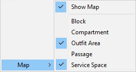
Map
You can select whether to show the model’s navigation map at the bottom of the 3D view. Depending on the model, there might be a number of different map types that allow you to choose whether to display blocks, compartments, service spaces, and so on.
When the navigation map is displayed, you can click the map to move the camera to the specified location. You can drag the upper-left corner of the map to resize the navigation map.
Smart Points and markups that are at the same floor or deck level as the user and inside the map area are shown in the navigation map.
For more information on maps, see Navigation map.
Show in VR
Show in VR opens the current eShare view in a separate Virtual Reality window. The window only shows the objects that are currently visible in eShare.
Note: VR view is available only in eShare App.
Using the VR view
You can open the eShare application window's view to a Virtual Reality headset (VR glasses) connected to the computer.
Prerequisites
- The Steam client and the SteamVR application by Valve. You can review the system requirements and download the application from the Steam store: https://store.steampowered.com/app/250820/SteamVR/.
- OpenVR headset such as HTC Vive, Oculus Rift, or Windows Mixed Reality.
Do the following:
-
Only the visible objects are displayed in VR. Showing fewer objects can make it easier to navigate and improves the performance—for best performance, send as few objects as possible to VR. Trying to open too many objects in VR at the same time shows a performance warning.
You can limit the number of objects to be shown by hiding the unnecessary objects or by using a clip box in eShare.
-
Navigate to the position from where you want to open the VR view.
-
Select Visualization Control > Show in VR. The CadmaticVR window opens and the active 3D objects are converted to the VR format (this can take some time).
Tip: If the VR does not seem to open, start the SteamVR application manually and then click Show in VR.
Now you can put on your VR headset.
-
You can use the VR controller to navigate in the model and select objects.
Note: Use the VR menu to switch between teleport mode (default) and normal movement.
Teleportation:
- Step forward by pushing the touchpad forward (shows a parabolic pointer) and then releasing it.
- Step backward by tapping the bottom of the touchpad.
- Rotate camera by pressing the side of the touchpad.
Movement:
- Move to a direction by tapping the touchpad. Move up or down by pressing the touchpad up or down.
- Rotate camera by pressing the side of the touchpad.
Object selection:
- Point the object with the VR controller and press the trigger button.
-
You can use a keyboard and mouse to navigate in the model and select objects.
Teleportation:
- Teleport to an object by right-clicking.
Movement:
- Move horizontally with W–A–S–D or arrow keys.
- Move up by pressing R or Space.
- Move down by pressing F or the left Ctrl key.
- Rotate camera with Q–E or by holding down the middle mouse button while dragging.
Tip: Default movement speed can be adjusted from the VR menu. Hold down the left Shift key to temporarily double your movement speed.
Object selection:
- Point and click with the mouse.
-
You can open the VR menu by pressing the VR controller's menu button or the Tab key.
The menu contains the following items:
-
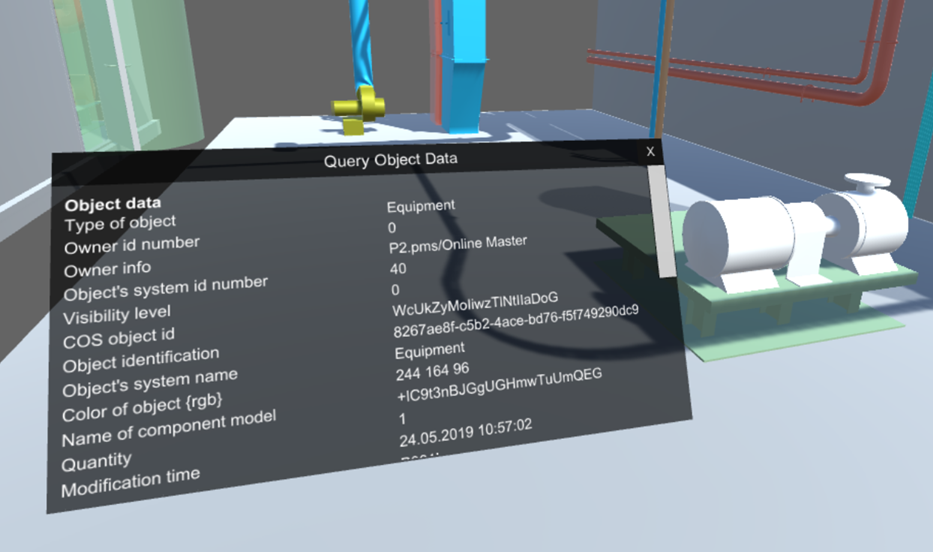
Query Tool – Allows viewing object data by pointing at an object and clicking. The Query Object Data dialog opens, showing the object attributes.
Note: Not all object attributes are shown in VR.
-
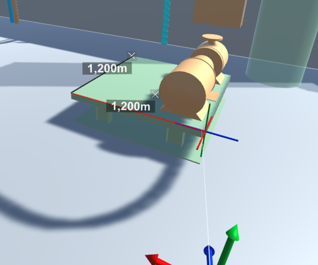
Measure – Allows taking measurements from the model by first pointing at an object and then clicking to select the first and the second measurement point.
You can specify the following settings:
- Snap to vertices – If selected, the measuring tool snaps to vertices.
- Snap to perpendicular – If selected, the measuring tool snaps to perpendicular lines.
Click Clear all measurements to remove all measurements from the VR view.
-
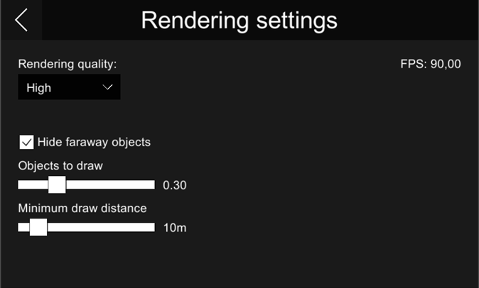
Rendering settings – These settings should be configured so that navigation is smooth at approximately 90 frames-per-second.
-
Rendering quality – Specify how detailed the VR view should be. Selecting higher rendering quality enables advanced features such as more detailed shadows, but it might decrease the performance.
-
Hide faraway objects – Hiding objects that are far away might improve the performance.
-
Objects to draw – Each model object is drawn using small triangles. This setting specifies the maximum amount of triangles to draw in "Hide faraway objects" mode. You can set the slider to a value between 0.1 – 1.0, where 1.0 means one million triangles.
-
Minimum draw distance – Objects that are closer than this value are always drawn, regardless of the "Objects to draw" setting.
-
-
-
Key Mappings – Allows changing the keyboard mappings.
-
Exit VR – Closes the CadmaticVR window.
Movement Settings
-
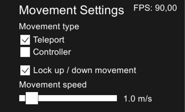
Movement type – Specifies movement type when using the VR controller (does not affect keyboard/mouse).
- Teleport – If selected, using the touchpad teleports the view forward or backward.
- Controller – If selected, using the touchpad moves the view in the specified direction.
-
Lock up / down movement – Locks the movement to be horizontal only. When disabled, you can move freely in the model.
-
Movement speed – Specifies movement speed when using the VR controller or the W–A–S–D keys.
-
FPS – Displays the current frames-per-second count.
-
-
If you change object visibilities or move to a different camera position in eShare, you can update the open VR view by selecting the Show in VR command again.
-
Close the CadmaticVR window by selecting Exit VR from the VR menu. You can also press Esc to show the exit dialog.