Point clouds
When revamping an existing building or ship so that some existing structures are removed and new ones are added, it is useful to be able to see how the old and the new structures will fit together. Point clouds allow you to do exactly that. If the existing structures have been scanned with a 3D scanner and the data is available as point cloud files, you can open the point clouds and the 3D models of the newly designed structures at the same time to see how they match. You can also use the Show Point Cloud Difference tool in Visualization Control menu. See Point clouds.
Note: Point clouds are always defined in project coordinates.
It is possible to show a hierarchy for the point clouds. The hierarchy is defined by eShare administrator.
You can toggle the visibility of the point clouds by clicking the eye icon.
Bubble view
Entering the bubble view mode moves the camera to the scanner position. You can rotate the view around this position, and you can zoom in or out with the mouse wheel. In panoramic view, you can move the camera by clicking the arrow marker, or focus the camera by clicking the rectangle.


There are various ways to open a bubble view:
-
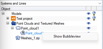
You can open the bubble view of a specific point cloud by right-clicking the point cloud in the object tree and selecting Show Bubbleview.
-
You can click the bubble view button in the main toolbar to open the nearest bubble view. If the button is not enabled, either the currently loaded point clouds do not have scanner position information, or a bubble view is already open.
-
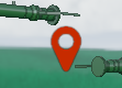
You can click a scanner position marker in the 3D view. You can do this also when a bubble view is already open, to move the viewpoint to another scanner position.
In bubble view mode, an additional toolbar is displayed at the top of the 3D view. The toolbar displays the name of the point cloud, a button for switching between point view and panoramic view, a button for orbiting around the scanner position, and a button for closing the bubble view. Closing the bubble view sets the viewing angle to where it was before entering the bubble view.

E57 file format feature support
CADMATIC supports reading the E57 feature categories XYZ, RAE, RGB, INT and MUL.
Support for E57 features
|
Feature Name |
Abbreviation |
Read |
Write |
|---|---|---|---|
|
Cartesian points |
XYZ |
Yes |
— |
|
Cylindrical imagery |
CYL |
— |
— |
|
Geodetic information |
GEO |
— |
— |
|
Multiple images |
MIM |
— |
— |
|
Multiple returns |
RET |
— |
— |
|
Multiple scans |
MUL |
Yes |
— |
|
Pinhole imagery |
PIN |
— |
— |
|
Point color |
RGB |
Yes |
— |
|
Point groups |
GRP |
— |
— |
|
Point intensity |
INT |
Yes |
— |
|
Spherical imagery |
SPH |
— |
— |
|
Spherical points |
RAE |
Yes |
— |
|
Structured point sets |
STR |
— |
— |
|
Time stamps |
TIM |
— |
— |
|
Visual reference imagery |
REF |
— |
— |
Support for E57 extensions
|
Extension Name |
Read |
Write |
|---|---|---|
|
ASPRS LAS format information |
— |
— |
|
Point normals |
— |
— |
For more information on E57 features, see http://www.libe57.org/features.html.