Generating bracket type files
CADMATIC AI allows you to generate bracket type files based on annotated drawings (image files) or textual requests.
Starting CADMATIC AI
CADMATIC AI can be started directly from CADMATIC Hull:
-
From the 3D-Contek application, Hull > Help > CADMATIC AI – Saving the generated files directly to the project norms is not possible.
-
From the System Management application, File > Help > CADMATIC AI – The generated files can be saved directly to the project norms.
See CADMATIC AI interface for information on the usage of the AI assistant.
Overview
Once the user has made a request in the AI assistant, the assistant shows a summary of the request, and lists the elements and variables to be included in the type file. Then it generates the type file and shows the file contents in the chat window. It also shows a Rechecking log which gives information about the file generation process.
You can request the AI assistant to make changes to the generated type file, iterating it further step by step. Every time you make a request for a change, the assistant will generate a revised type file.
When CADMATIC AI is started from the System Management application with administrator rights, it is possible to save the generated type file directly to the project norms. The Hull system will create a basic type macro to be used with the type file. The type macro is a basic one and does not contain values for the variables. The system-generated type macro can be used as a basis for the final type macro. If this type macro was not edited to define the values for the variables, a Bracket type dialog showing the variables opens when the AI-generated bracket type is placed into a view. The user must enter the desired values in the input boxes next to the variable names.
When the CADMATIC AI is started from 3D-Contek, or from System Management with read only rights, it is not possible to save the generated type file directly to the project norms.
Important: Before using an AI-generated type file, check the type file and make sure that it is fit for its intended purpose. Also ensure that the associated type macro (the type .cmd file) is in place and defines all the necessary variables for the type to work as intended.
When started from System Management with administrator rights, the generated type file can be saved directly to the project norms. In this case the Hull system creates a basic type macro for the type file. The system-created type macro does not contain variable values.
See also Correcting and changing bracket type files.
Creating annotated images and textual requests
Consider the following bracket properties when creating annotated images and textual requests for creating bracket type files:
-
How many relations should the bracket have?
-
Are the bracket's dimensions along the relations user-defined of fixed size?
-
What kind of elements should the geometry of the contour have?
-
What should be the description of the bracket?
Annotated images
When you use annotated images as the basis for the type file, use the following type of request, and add the annotated image:
Create a type file for the bracket in the image.
The request does not have to be formulated exactly as above.
Geometric precision of the image is not required. CADMATIC AI uses the text (annotations) in the image, not the drawn geometry. The image serves merely as guidance for the human to formulate the annotations.
Describe the relations, dimensions and other properties of the bracket geometry in the annotations. Include the bracket description. The annotations should be similar to the instructions in textual requests. See the examples in Textual requests.
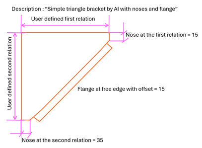
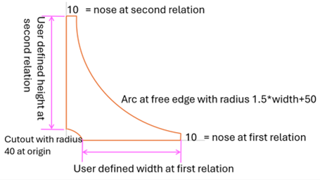
Note: Do not use annotations consisting of just numbers, without mentioning the geometric property. For example, using just "35" for a nose will not be enough. Instead use a phrase like "Nose at first relation, size 35".
Textual requests
You can use text-only requests to generate bracket type files. Textual requests consist of instructions for the AI assistant to create the type file. Similar instructions can be used as annotations when generating type files from images.
The instructions should describe the relations, dimensions and other properties of the bracket geometry. See Phrases for describing the bracket geometry. Your complete request should consist of instructions describing the desired geometry step by step.
Important: When pasting a complete request or an input that consist of several instructions, separate the instructions from each other by using a full stop, colon or semicolon. A line break alone will not work as a separator.
Each of the examples below represent a request with instructions.
 Show/hide Example 1
Create a type file for a bracket with two relations and the following properties:
Width of the bracket along the first relation is user defined.
Nose at the first relation of size 15.
Flange at the free edge with offset 15.
Nose at the second relation size of 35.
Height of the bracket along the second relation is user defined.
Snipe at the origin of size 35.
The description of the bracket is "By AI".
Note: The creation of the flange at a free edge may be dependent on the size of the created bracket. This depends on the associated type macro.
Show/hide Example 2
Create a type file for a bracket with two relations and the following properties:
Width of the bracket along the first relation is user defined.
Nose at the first relation of size 50.
Cutout of radius 35 at the nose at the first relation.
Flange at the free edge with offset 5.
Cutout of radius 35 at the nose at the second relation.
Nose at the second relation size of 50.
Height of the bracket along the second relation is user defined.
The description of the bracket is "By AI. Cutout at nose at the 1st and 2nd relations".
Show/hide Example 3
Create a type file for a bracket with two relations and the following properties:
Width of the bracket along the first relation is user defined.
Nose at the first relation of size 10,
arc at free edge with the radius 1.5*R1+50.
Nose at the second relation of size 10.
Height of the bracket along the second relation is user defined.
Cutout of user defined radius at the origin.
The description of the bracket is "Bracket by AI with arc at free edge".
Show/hide Example 4
Create a type file for a bracket with two relations and the following properties:
Width of the bracket along the first relation is user defined.
Snipe of size 15 at the end of the first relation.
Nose at the first relation of size 30.
Flange at the free edge with offset 5.
Nose at the second relation size of 30.
Height of the bracket along the second relation is user defined.
The description of the bracket is "By AI. Snipe at the end of the first relation".
Show/hide Example 5
Create a type file for a bracket with three relations and the following properties:
Height of the bracket along the first relation is user defined.
Nose at the first relation of size 15.
Flange at the free edge with offset 5.
Stop-distance 25.
Height along the stopping relation 100.
Snipe size of 55 at stopping relation.
Cutout at the origin with radius 75.
The description of the bracket is "Bracket by AI."
Show/hide Example 6
Create a type file for a bracket with four relations and the following properties:
Stop-distance 25 at stopping relation along the first relation.
Height along the stopping relation 20.
Flange at the free edge with offset 5.
Stop-distance 25 at stopping relation along the second elation.
Height along the stopping relation 20.
The description of the bracket is “Bracket by AI. Four relations."
Phrases for describing the bracket geometry
The table below lists phrases describing the bracket contour elements which make up the bracket geometry. You can use these phrases in the requests you make to CADMATIC AI. These phrases are examples. It is not necessary to use this exact phrasing.
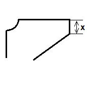
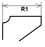
Illustrations are provided to help you design annotated images matching the phrases.
| Nose at the first relation of size x |
|
|
User defined length along the first relation User-defined width of the bracket along the 1st relation User-defined height of the bracket along the 2nd relation In case of fixed size: Length along the first relation of size 500 Width of the bracket along the first relation is 400 |
|
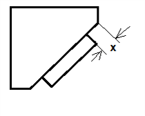
| Flange at the free edge with offset x |
|
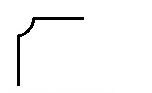
| Cutout at the origin with radius... |
|
|
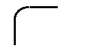
Rounding at the origin with radius... |
|
|
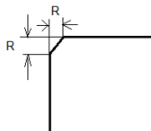
Snipe at the origin of size... |
|
|
Rounding at the end of the 1st relation with radius… |
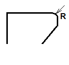
|
|
Cutout at the end of the 1st relation with radius… |
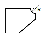
|
|
Snipe at the end of the first relation size... |
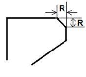
|
|
Rounding at the nose at the 1st relation with radius… |
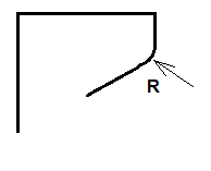
|
|
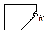
Cutout at the nose at the 1st relation with radius… |
|
|
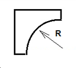
Arc at free edge of radius... |
|
|
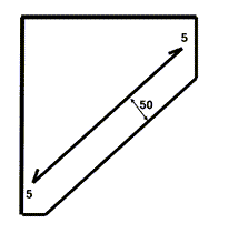
Profile parallel to free edge at distance 50 with offset 5. |
|
|
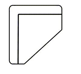
Overlap at the second relation size of 4 times the bracket thickness. Overlap at the first relation size of 4 times the bracket thickness. Overlap at the second relation size of 20. |
|
|
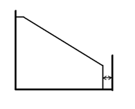
Stop-distance. Distance to stopping relation. |
|
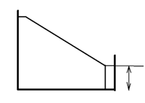
| Height along the stopping relation |
|