Shell Frames
Construction > Insert > Shell Frames

Create shell frames in longitudinal directions. Select from the following options:
Fixed Angle to Shell – Create shell frames with a fixed angle relative to the shell.
With Fixed Angle to Base – Create shell frames with a fixed angle relative to the base line.
With Fixed Height – Create shell frames with a fixed height value.
With Fixed Width – Create shell frames with a fixed width value.
Cross Shell Frames – Create cross shell frames.
Creating shell frames
-
In the first dialog, select the main location/orientation and the profile type of the shell frame.
 View/hide screenshot:
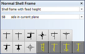
The 1st dialog with default values when inserting Cross Shell Frames.
-
In the second, Location and dimensions dialog, define the shell frame properties such as dimensions, offsets, and thickness and body directions. The selections in the dialog vary according to the shell frame type. Here you can also select to make the shell frame a composite profile (see Composite profiles).
View/hide screenshots:
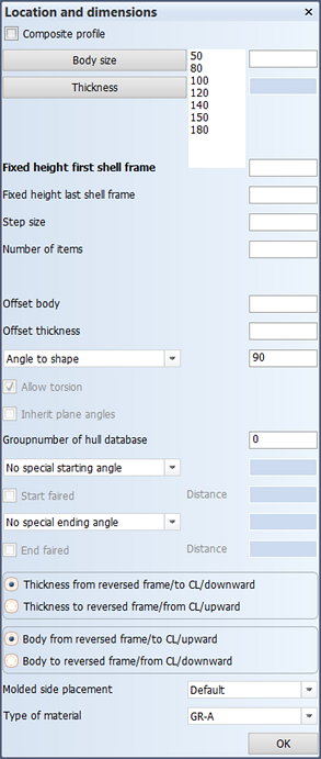
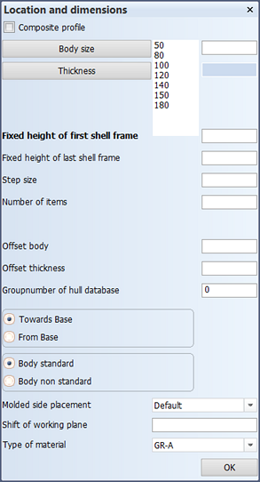
Location and dimensions dialog when inserting Fixed Angle to Shell or Fixed Angle to Base shell frames. Location and dimensions dialog when inserting shell frames With Fixed Height or With Fixed Width, or Cross Shell Frames. -
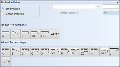
In the third dialog, define the limitations and endtypes.
See Creating shell frames in longitudinal directions in the Modeling Construction Items User's Guide for more detailed information on how to create shell frames in longitudinal directions.