Composite profiles
When a profile is a composite profile, the system treats it as complete construction item but its body and flange will be coded separately.
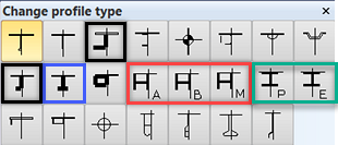
The profile types that can be defined as composite profiles include the following:
|
|
The profile types marked with a black or blue frame have one body and one flange. The profile types marked with a red or green frame have one body and two flanges.
The image below shows what part of the profile is considered as body and what parts are considered as flanges.
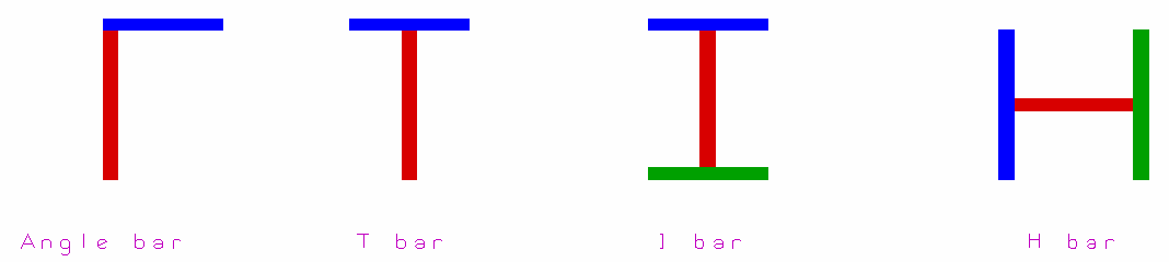
- red – body
- blue – first flange
- green – second flange
Creating composite profiles
To design a profile as a composite profile, select the Composite profile option in the Create Profile dialog when inserting the profile with the Profiles in View function.
When modifying profiles, the Composite profile option is present in the Change profile type dialog, provided that it is applicable to the profile type, and you can either select or clear the option there. See Construction > Profiles > Modify > Size/Type for more information.
In case the profile type you selected is not available as composite profile, the Composite profile option cannot be selected. In case you selected the composite profile option the first time when you created a profile, the option will be automatically selected the next time you use the Insert Profile function.
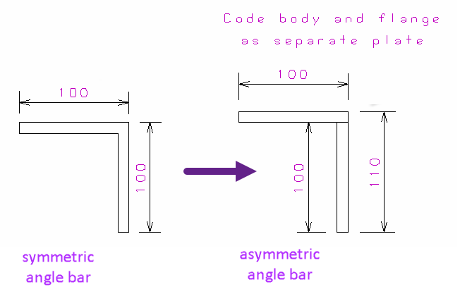
Note: When you select the Composite profile option for an equal angle bar during the creation or modification of a stiffener, the system will automatically save it as an unequal angle bar to allow the coding of the flange and body separately. See image below for demonstration:
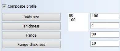
When you leave the Composite profile check box cleared, H and I profiles have one dimension, unequal angle bar and T-bar have three or four dimensions, depending on the settings defined in Construction > Profiles > Dimensions in the System Management application. When you select the Composite profile option, the dialog box allows you to edit all four dimensions for the unequal angle bar, T-bar and H- and I-bars. Note that the height for the angle, T- and I- bars are the inner heights and the flange size for H-bars have the inner dimension.
In case no dimensions are defined here, the system uses a set of default dimensions for the profile.
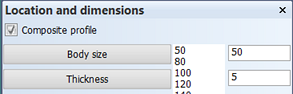
Composite shell frames: Shell frames can also be composite profiles, but H and I types are not available. When inserting a shell frame in the Shell and 3D-Show applications, select Composite profile at the top of the Location and dimensions dialog (2nd dialog):
Composite pillars: Pillars can also be composite profiles, both in case the active block is the owner, and in case the neighbor block is the owner.
Presentation of composite profiles
3D-Item Information
You can check if the profile is a composite profile in the Type and Production method of the profile in the Geometry section of the 3D-Item Information.
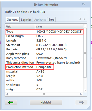
In case of a non-composite profile, the Type field of the 3D-Item Information shows the attributes set in the Presentation > Profiles > Dimension Text settings of the System Management application. By default the 3D-Item Information shows the type and dimensions of the profile.
In case the profile is a composite profile, the system ignores the Dimension Text settings and displays the dimensions that the profile was created with:
<body size>X<body thickness>/<flange size>X<flange thickness>
Part labels
By default, profile part labels display the profile either with profile type or profile name, depending on the settings in Presentation > Profiles > Dimension Text.
For non-composite profiles
-
Profile type in the part label: The main dimension (name) is shown.
-
Profile name in the part label: All dimensions are shown if the configuration allows it.
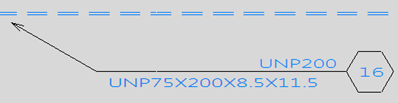
For composite profiles:
- Profile type in the part label: Only the four dimensions are shown (not part numbers), as they have been defined in the System Management application, Presentation > Profiles > Dimension Text
- Profile name in the part label: Only the outer dimensions are shown.
Settings defined in the Presentation > Profiles > Dimension Text in the System Management application overwrite the default configuration.
Reports
A report indicates if a profile or shell frame is a composite profile. Parts of composite profiles are presented in separate lines, as follows:
- Angle bars and T-bars are listed in two lines, the body and flange in separate lines.
- H-bars and I-bars in three lines. The body is listed in one line, and the two flanges are listed both in a separate line (as in the picture below).
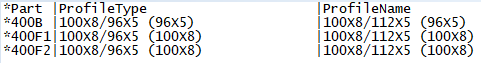
All data in the different columns are the same as for non-composite profiles, except in the derived data fields ProfileType and ProfileName, and in the logistical data fields PartNumber, Width, Thickness, Flange, and FlangeThickn.
Partnumbers of the body and flange parts are presented with the prefix and postfix defined in the System Management application, Production > Plate Cutting Data >Settings.
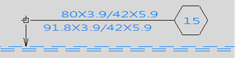
The Profile type consists of (a possible) shorter name than the profile name. Also here the breath and thickness of the individual parts are added to the profile type.
The profile name consists of the full name, and the breath and the thickness of the individual part between parentheses. The image below shows an example of a T-bar with a 250X10.5 body and a 125X15 flange.
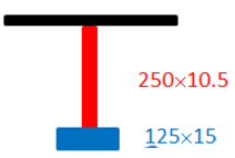
- The body is presented by 265X125/15X10.5 (250X10.5). The first value of the full name is the height of the body (250) + the thickness of the flange (15), or in case of two flanges 2 times the thickness of the flange.
- The flange is presented by 265X125/15X10.5 (125X15).
Dimensions (Length, Width, Thickness, Flange, FlangeThickn): The length is the same in all lines, and the length and thickness values contain the dimensions of the individual parts. Flange and FlangeThickn contain 0 because the individual parts do not have flanges.
Weight – The following formulas are used to present the weight of the composite profile:
- Body: length * body height * body thickness * specific weight
- Flange: length * flange width * flange thickness * specific weight
These weights are only used for presentation purposes, and are not used in the calculation of the total weight. The actual weight of the profile is used in the calculation of the total weight.
The Center of gravity is the one from the complete part. Also the total center of gravity of all parts in the report is the same as for the original parts.
For more information on coding composite profiles and shell frames, see Coding composite profiles and shell frames.
XML export and import of composite profiles
The logistical information for each part of a composite profile is saved as a separate line in the exported XML file.
When importing an XML file that contains composite profile data, all the lines representing the parts are imported to the logistical database, provided that the lines are in an editable logistical field.
After importing, the parts should be recalculated.
Coding of composite profiles and profile sketches
The coding of composite profiles will produce two or three DXF files depending of the profile type. See Coding composite profiles and shell frames for more information on coding composite profiles.
A composite profile must be coded before the profile sketch can be created because the flange part in the profile sketch is taken from the flange DXF file. See Profile sketches for composite profiles for more information.
The coding and sketch creation can be performed at the same time by selecting both Code block and Sketches in the Create Production Information dialog. See Create Production Information.
Note: If the composite profile has a face plate as a flange, the system will generate separate sketches for the body and face plate.