Hole Parallel to Line Related
Construction > Insert > Holes > Parallel to Line > Hole Parallel to Line Related

Create holes at a specified parallel distance to a line. The holes will be related to the surrounding construction (bulkheads, decks and hull lines).
Do the following:
-
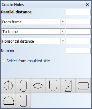
Select Construction > Insert > Holes > Parallel to Line > Hole Parallel to Line Related. The Create Holes dialog opens.
-
Indicate at the side of the line along which to position the holes. Boundaries of plates in cross section and hull lines can be selected.
If you indicate the boundary of a plate split by seams (panel), the holes will be related to that plate part of the panel which is nearest to the indication point. See Holes in plates split by seams.
-
Specify the position of the holes by entering the values for the following fields:
-
Parallel distance – The distance between the center of the holes and the line
-
From frame, length, breadth or slanted grid – The position of the aft most hole.
-
Sequential distance – The distance between the holes.
-
Number – The amount of holes to be created.
-
Select from moulded side – When this option is activated, only the moulded side boundaries of plates can be selected; the lines at thickness side cannot be selected. Hull lines can always be selected.
You can define another series of holes by clicking Next series. Then enter the values for the new series.
-
-
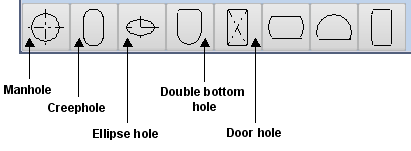
Select the hole type. The five leftmost hole types are standard holes. From left to right these are types 1, 2, 3, 5 and 6 (type 4 is not used), and named in the image below. The rest of the hole types are user-defined holes (the type numbers can range from 8 to 99).
 Show/hide image
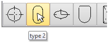
You can see the hole type number when you move the mouse pointer over the hole icon.
-
Click OK to create the holes.