Vertical
To create perpendicular plates below a plate in view vertically, go to Construction > Plates in the 3D-Contek application.
You do not have to select the plate in view. The system automatically determines the main plate, and relates the perpendicular plate to all the plates in view that it crosses, in counter-clockwise order. The plates that the system considers for relating to the perpendicular plate depends on the visibility settings. A plate in view should have all its corners within the viewing area to be considered. If there are no plates in view, the system checks if there are plates above the current view, and if not, then determines fixed border values for the perpendicular plate.
Note: If in any view, you create a vertical sub-bulkhead defined by only 1 fixed value limit relation, the sub-bulkhead will not be created. This is because there is not enough information regarding the direction of the sub-bulkhead.
Do the following:
-
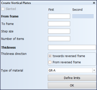
Select Insert > Vertical.

The Create Vertical Plates dialog opens (opened from top view here so the vertical direction is frame).
-
Select the limitations (From/To) for the plates to create, and enter the Step size and the Number of items to create.
Note: The plate limitations can be defined by selecting the grid value using mouse buttons. The From value is chosen with the left mouse button and the To value with the right mouse button.
-
Enter the Thickness, and select the Thickness direction and Type of material for the plates.
-
Define limits – Define limits for the lateral plate borders (optional). Select the limiting construction parts in the graphical window, or enter a limiting perpendicular value.
- If you do not define the limits, the hull line or the drawing limits will be used as the limits, whichever is smaller.
- You can select only one limit. In this case the system automatically determines the other limit. It is not possible to select just one limit if it is along the length direction however.
-
Click OK to create the plates. The plates are created according the selected fixed values, stopping at the edges of the plates.
Note: If the plate shape is such that a vertical line intersects several points in the plate contour, the two most extreme points are used.
Tip: You can add a series of stiffeners to the plates using the Construction > Profiles > in Section functions. See Creating profiles in section.