Creating profiles in section
The Profiles in Section functions are typically used for adding stiffeners to plates that act as bulkheads between decks. A series of evenly distributed profiles can be added in one go to one or more plates. You can add profiles to plates in cross section in two ways: In the normal way as actual profiles, or as plate properties. Profiles as plate properties must be converted to actual profiles before the production phase.
Note: In Plant Modeller, hole requests cannot be created for profile properties. When the profile properties are converted to regular profiles before the production phase, hole requests can be created as necessary. See Profiles as Property.
To add profiles to plates in cross section, in the 3D-Contek application select Construction > Profiles > Insert > in Section, and one of the following functions:
- Profiles in Section – See Profiles in section below.
- Profiles in Section as Property – See Profiles in section as property below.
Profiles in section
To add profiles to one or more plates in cross section, do the following.
-
Select Construction > Profiles > Insert > in Section > Profiles in Section. The Plate Selection dialog opens.
 Show/hide image
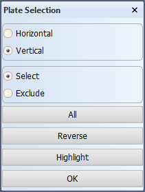
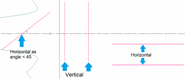
The default selection is Vertical in the top view, and Horizontal in the side and frame views.
-
Select one or more plates in cross section to add profiles to. The selected plates must be in the same direction, that is, they all must be either horizontal or vertical. A slanted plate is considered horizontal if its angle to the x-axis of the view is less than 45 degrees, otherwise the plate is considered vertical.
In perpendicular views, the profile direction will always be in the closest orthogonal direction to the plane of the view.
- Select Horizontal or Vertical. Depending on the selection, only horizontal or vertical plates can be selected.
- Select the plate(s) in the graphical window.
-
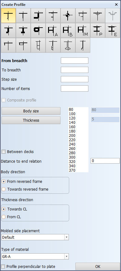
Click OK. The Create Profile dialog opens (top view case shown here):
Define the following:
Profile types – Select the profile type to add. The thumbnails show the structure of each available profile.
Fixed values – Horizontal or vertical profiles always have four relations: two fixed values and two user defined relations. You can click the frame numbers or grid lines in the drawing to define the fixed values. Click with the left mouse button to set the start value, and the right mouse button to define the end value.
Composite profile – You can code bodies and flanges for certain profile types separately, while the design system still treats the profile as one complete construction item. These profiles are called composite profiles. For more information, see Composite profiles.
Body size and Thickness – Set the size and thickness for the body of the profile.
Flange and Flange Thickness – Set the size and thickness for the flange of the profile. These settings are only available for composite profiles.
Between decks (top view) or Between bulkheads (side and frame views) – When selected, the added profiles are limited between the two closest plates in the depth of the viewing plane (in the view direction).
Show/hide example
Profiles in section are added in side view. There are two bulkhead plates (1) in depth of the viewing plane. In the image below, the situation is seen from the top.
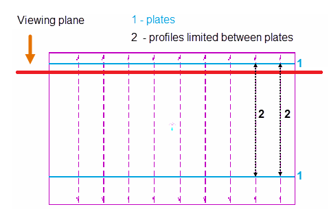
When the Between bulkheads option is selected, the profiles (2) are limited by the bulkhead plates, not by the deck plate borders.
Distance to end relation – Define the distance of the profile ends to the plate boundary.
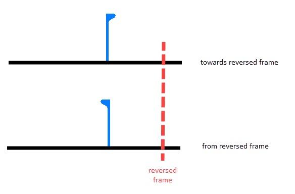
Body direction – Define the orientation of the body. The orientation can be either from or towards the reversed frame.
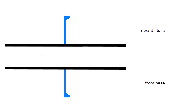
Thickness direction – Set the thickness direction of the profile. The thickness direction can be either towards or from the base (horizontal profiles), or towards or from the center line (vertical profiles).
Molded side placement – This setting sets the molded side of the profile. By default a profile is placed by its molded side. It is possible that the profile is not aligned as desired with the construction item that is located on the other side of the plate, if both parts have the default thickness direction. This is because it is the molded lines of the parts that are aligned. By changing the molded side placement it is possible to change how the profile is aligned with the construction item that is located on the other side of the plate. The molded side position can be changed from the default to the midpoint of the profile body, or to the thickness side of the profile.
Show/hide image
The image below shows the three available options:
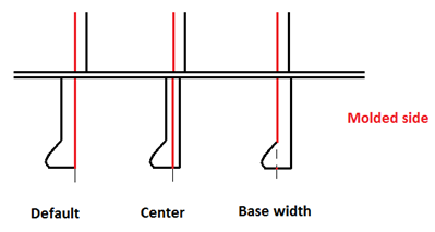
See Molded side placement for profiles for more information.
Type of material – Select the material type of the profile.
Profiles perpendicular to plate – In case of a slanted plate, the profiles are created perpendicular to the plate instead of horizontal or vertical.
- Click OK. The profiles are created for the selected plates at the desired positions. Each profile has a relation to the plate in cross section.
Notes:
-
Profile end relations are determined by the plate limitations.
-
Profile end types are generated automatically according to the end type definition rules. The end types can be modified later.
Profiles in section as property
Add profiles to plates in cross section as plate property instead of actual profiles. This function is best suited for situations where many changes are likely to take place during the basic design, and the system uses a lot of automation to adjust the construction parts.
Adding plate stiffening using the Profiles in Section as Property function allows the stiffening to follow the changes in the size of decks and bulkheads. When a deck or bulkhead becomes smaller or bigger, the system automatically reduces or increases the number of stiffeners (profiles), respectively.
The profiles are contained as sub-attributes in the Profile as Property plate attribute. The system adds the profiles at the default grid values. Where there is no room for a profile contained in a Profile as Property attribute because a regular profile or other construction already exists at the grid value where the profile would be added, the profile is not created. The Profile as Property attribute is created even if no profiles can be added. When the plate is recalculated, after lengthening or shortening it for example, the system creates profiles according to the Profile as Property attribute where there are free grid positions, and removes profiles from positions where there is no longer room for them.
When calculating the weight or the center of gravity (CoG) of the plate, the system adds the profiles as properties to the plate's weight/CoG.
Notes:
-
Profiles are not created within a half grid distance to a parallel part of the plate boundary, in positions where a plate in cross section exists, or in positions where a regular profile with the same body direction already exists. Also, the profile must have the minimum length set in System Management > Construction > Profiles > As Plate Property > Minimum Profile Length. Profiles shorter than the minimum length will not be created.
Because of these conditions, modifying (and recalculating) the plate may result in profiles being removed or added. -
A plate can only have one Profile as Property attribute. When a profiles as property attribute is added to plate that already has one, the new attribute replaces the old one.
-
If a regular profile is added to the plate which already has a Profile as Property attribute, the attribute will remain. For information on how to remove profiles as properties, see Removing profiles as properties below.
-
In Plant Modeller, hole requests cannot be created for profile properties. When the profile properties are converted to regular profiles before the production phase, hole requests can be created as necessary. See Profiles as Property.
Important: Profiles as plate properties must be converted to actual profiles before the production phase. See Profiles as Property.
See also 3D-Item information for profiles as plate property below.
Adding profiles as property
To add profiles to one or more plates in cross section, do the following:
-
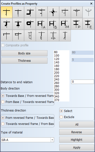
Select Construction > Profiles > Insert > in Section > Profiles in Section as Property. The Create Profiles as Property dialog opens.
-
Select one or more plates in cross section to add profiles to.
-
Define the following:
Note: You do not select any position for the profiles as property. They are automatically added to the default grid position. A default grid must be defined. The system will shown an error message if there is no grid defined.
Profile types – Select the profile type to add. The thumbnails show the structure of each available profile.
Composite profile – You can code bodies and flanges for certain profile types separately, while the design system still treats the profile as one complete construction item. These profiles are called composite profiles. For more information, see Composite profiles.
Body size and Thickness – Set the size and thickness for the body of the profile.
Flange and Flange Thickness – Set the size and thickness for the flange of the profile. These setting are only available for composite profiles.
Distance to end relation – Define the distance of the profile ends to the plate boundary.
Body direction – Define the orientation of the body. The orientation can be either from or towards the reversed frame.
Thickness direction – Set the thickness direction of the profile. The thickness direction can be either towards or from the base (horizontal profiles), or towards or from the center line (vertical profiles).
Type of material – Select the material type of the profile.
-
Click Apply. The properties are added to the selected plates.
-
You can continue selecting plates in cross section and adding profiles as property. Click Apply each time you want to add the property.
To close the dialog, press Esc or click the Close button at the top of the dialog.

3D-Item information for profiles as plate property
When profiles are added to a plate as a property, the plate gets a Profile as Property attribute, which is shown in the Attributes tab of the 3D-Item Information dialog.
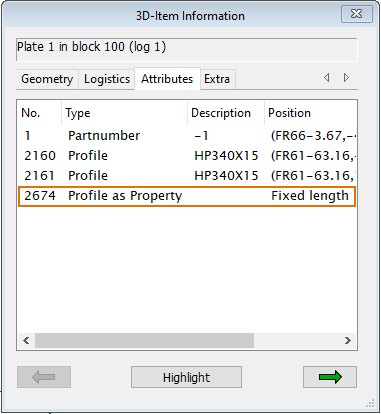
The individual profiles are sub-attributes to the Profile as Property attribute. To see a list of the individual profiles (sub-attributes), select the Profile as Property attribute, and click the right arrow in the dialog. You can also select any profile that belongs to the Profile as Property attribute in the graphical window while the 3D-Item Information dialog is open.
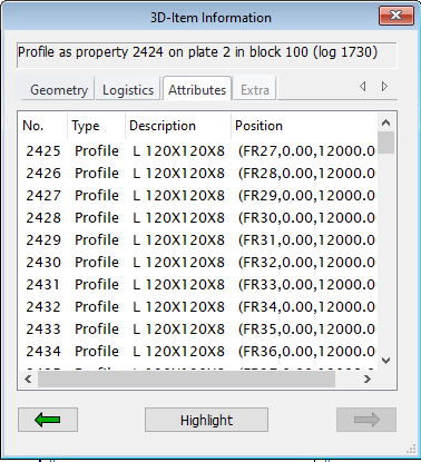
Each profile belonging to the Profile as Property attribute is listed in the dialog. The Geometry, Logistics and Attributes tabs are available for the Profile as Property. The Position field in the Attributes tab shows the grid values at which the profiles are created.
To view the 3D item information of an individual profile, select the profile in the Attributes tab, and then click the right arrow.
Removing profiles as properties
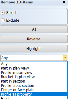
Profiles as plate properties can be removed with the Remove 3D-Items function. All the profiles belonging as Profile sub-attributes to the same Profile as Property main attribute will be removed.
Do the following:
-
Select Remove from the General group of the menu.

-
In the graphical window, select a profile that has been added as plate property.
You can use the selection filter to help select profiles added as property.
All the profiles belonging to the same Profile as Property attribute are selected and highlighted in the graphical window.
-
Click OK. The Profile as Property attribute and all the Profile sub-attributes are removed from the plate properties.