Aft View
Home > Create > Aft

Create a new aft shell view (frame view). An aft view presents a user-defined area in length direction. You can define the area, scale, and view direction of the view, and select which hull groups are visible in the view.
You can also select which items are shown in the view: hull lines, 3D construction, weld lines, centre line and base line. The centre line and the base line can placed at an offset.
For step-by-step information on how to create shell views, see Creating shell views in the Shell Plates Reference Guide.
Settings and options in the Shell View dialog
Views – Preselected according to which view was selected to start the view creation. You can switch the view, from an orthogonal view to a slanted one, for example.
Selecting a slanted view activates the input fields for defining the coordinate points of the viewing plane. The coordinate points set the position and angle of the viewing plane. Grid values and values in mm can be used. Only the relevant fields are active for each slanted view type.
View type – Sets the type of the view. The following types can be selected:
- Standard – Views the ship from the side, projecting it onto a single plane.
- 3D Aft – Views the ship from the side and aft direction at a fixed angle of 45 degrees, starboard side.
- 3D Fore – Views the ship from the side and front direction at a fixed angle of 45 degrees, starboard side.
- 2D Expansion – Creates a 2D shell expansion. Only available for side and top views. See 2D shell expansions.
Hull groups – Sets one or more hull groups visible in the view. All the hull groups present in the shape database are displayed in the drop-down list, and each can be chosen to be added to the view. When hull lines are added to a view showing multiple hull groups, the system asks the user to specify the hull group for which the hull lines are created.
Note: Only one hull group can be selected when creating a 2D shell expansion.
Area settings – Sets the limits for the view area. The area can be set by entering the limits in the length, breadth and/or height direction. The fields are prefilled with the last used values.
- Jig planes (optional) – If template sets have been defined with the "Jig" production property, the Views list is extended with the Jig plane option. Selecting this option will show an additional list of template sets with the "Jig" property in the Area settings section. Selecting one of these templates sets will set the view area limitation to the values of the corresponding optimum jig plane.
- Area ship – Sets the view area limits to match the size of the hull shape.
- Block area – Sets the view area limits to match the area limits of the active block. When the area limits of the block are unknown, the area of the ship is used.
Additional content – Sets which additional content is shown in the view.
- Show hull lines – Shows the hull lines in the view, such as knuckles, butts and seams, if present.
- Show construction – Shows the 3D construction in the view, if present.
- Show weld lines – Presents the weld lines in the view, if present. This setting requires that the construction is shown as well.
- Centre line – Displays the centre line in the view. The centre line can only be seen in aft views, top views and certain slanted views.
- Base line – Displays the base line in the view. This line can only be seen in aft views, side views and certain slanted views.
- Position – Places the corresponding line at an offset. When left empty, the line is left at its default position.
- Step – Sets the interval at which the numbers along the centre/base line are displayed. When left empty, the interval defaults to 2, which means that a number is added every other frame. Not available in the aft (frame) view.
- Ps up – Applicable only to 3D Aft and 3D Forward views. Changes the view perspective to port side.
View direction towards – Sets the viewing direction, relative to the angle of the current drawing. When construction is shown with a dashed line, the viewing direction is from the outside of the ship looking inwards. When construction is shown with a solid line, the viewing direction is from the inside of the ship looking outwards.
- Foreship – View direction is from aft to fore. Applicable to aft views and slanted views.
- Aftship – View direction is from fore to aft. Applicable to aft views and slanted views.
- Starboard – View direction is from port side to starboard. Applicable to side views and slanted views.
- Port – View direction is from starboard to port side. Applicable to side views and slanted views.
- Top – View direction is from bottom to top. Applicable to top views and slanted views.
- Bottom – View direction is from top to bottom. Applicable to top views and slanted views.
When the selected View type is 2D Expansion (available for side and top views), the options are:
-
Standard – View direction is from the outside of the ship to the inside. Construction on the outside of the ship is shown as drawn, and construction on the inside as dashed.
-
Non-standard – View direction is from the inside of the ship to the outside. Construction on the inside of the ship is shown as drawn, and construction on the outside as dashed.
In Shape Import the orientation of the surfaces is indicated by colours. The outside of the ship appears in gold, and the inside in jade.
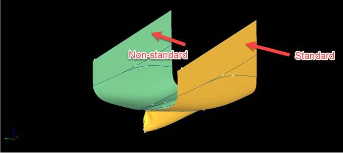
View directions in Shape Import
Scale – Sets the scale of the drawing.
Drawing number – Sets the drawing number.