DXF Templates to Sketch
Production > Production > Template to Sketch

Creates sketches of coded shell plate templates. It is possible to create one template sketch of all the templates of a shell plate. When templates have been created on the inside and outside of a shell plate, the system will create template sketches of both sides.
A template sketch consists of pictures of the selected templates and their dimensions, and a table containing dimension measurements for each template.
-
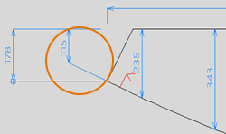
Dimensions in the template pictures are always related to the outer contour of the template.
-
The shape of the template is extended outside of the template border with a small line that has the length of one grid step size. The same pen is used for the line as for the dimension lines. An extra dimension line is also added for the extension line.
-
It is possible to use the same template set for shell plates that are mirrored over the center line, as the system mirrors the marking symbols also on the template.
-
The dimension measurements in the table are calculated and presented by steps of distance defined by the Step size setting. Step values are presented at the top of the table.
-
The dimension measurements in the table are based on the sight line plane (default) or the lowest height (when Table measurement from base is selected in settings).
-
The width of the table is automatically adjusted according to the widest template.
The layout for template sketches can be defined in the System Management application, Production > Template Sketch > Sketch Layout.
To ensure that all dimensions in template sketches are presented correctly, do the following:
- When creating template sets, enable perpendicular template contours by selecting the Templates contour perpendicular to sight plane option in the Create templates for plate dialog (Templates Wizard). See Templates wizard: create templates for plates for more information.
- Use two angle markings. This is defined in the Number Of Angle Markings setting in System Management > Production > Templates > Shell Plates > Marking. Two is the default setting.
- Set the length of the angle marking line to less than the template minimum height. This is defined in the Angle Marking Length setting in System Management > Production > Plate Cutting Data > Marking > Angle of Connecting Parts.
Main tab
Select the templates to include in the template sketch.
- Show mode – Select the templates one by one. The selected template is shown in the graphical window. You can filter the list by a string in the file name, and move up and down the list by using the Previous and Next buttons above the list.
- Select mode – Select one or several templates. Use the To Select and All to Select buttons below the list. Deselect by using Out Selection and All out Selection.
- Show Sketch if present – When checked, displays the whole sketch if it is present.
To generate the template sketch, click OK.
View and Plot tab
View and plot template sketches generated in the Main tab, or delete them. You can filter the list by a string in the file name, and move up and down the list by using the Previous and Next buttons above the list.
- View part sketch – The selected sketch is displayed in the graphical window.
- Delete part sketch / Delete ALL part sketches – Deletes the selected or all sketches.
- To drawing mode – Quit the DXF Templates to Sketch dialog temporarily to edit a template in the graphical window. Save the edited template to return.
- Plot sketch – Plots the selected sketch(es).
- Plot all sketches – Plots all the sketches on the list.
Settings tab
These settings define how dimensions and measurements are presented in the graphical window and in the template sketch.
- Margin from plate – Sets the distance between the plate edge and a dimension.
- Margin dimension – Sets the distance between chain dimensions. Applicable only when the selected dimension type is Chain dimension.
- Dimension type – Defines the dimension type that is used, Chain dimension or Absolute dimension. When Absolute dimension is selected, starting points for the horizontal and vertical dimensions can be chosen:
- Top horizontal from left – Select this to have horizontal dimensions above a template to start from left. Clear to have the dimensions start from right.
- Bottom horizontal from left – Select this to have horizontal dimensions below a template to start from left. Clear to have the dimensions start from right.
- Left vertical from below – Select this to have vertical dimensions on the left side of a template to start from below. Clear to have the dimensions start from the top.
- Right vertical from below – Select this to have vertical dimensions on the right side of a template to start from below. Clear to have the dimensions start from the top.
- Significance – Sets how many decimal digits are displayed in the dimensions.
- Pen number dimension – Defines the pen number for text in the dimensions.
- Character Height – Defines the character height for text in the dimensions.
- Arrow type – Defines the arrow type and size for the dimensions. The first digit defines the arrow type. The second digit defines the arrow head size. The digits must be separated by a comma. Character "a" directly following the second digit indicates absolute size in mm, otherwise the size is in relation to the scale of the drawing.
- Skip parts smaller than – Defines the minimum size of templates to include in the sketch. Smaller templates will not be included even if selected.
- Step size – Sets the distance step size for dimension measurement points in the table.
- Sight shift – Adjusts all the height values in the table. The dimensions in the pictures remain unchanged. When set to 0 (default), the measurements in the table match the dimensions in the template pictures.
- Maximum Templates – Defines the maximum number of templates that are presented below each other. If more templates are selected, a new column is created to accommodate all the templates.
- Table measurement from base – Defines the reference point for dimension measurements in the table.
- When cleared: Dimensions are measured from the sight plane.
- When selected: Dimensions are measured from the lowest height (base).
- Save part with dimension into separate dxf – Save the templates with their dimensions to a special folder, dxfsketch. This folder will be a subfolder to the folder where the coded parts are saved. It is possible to use the dimensions in templates saved with this function in Nestix.
Template sketches for flexible templates
The table in the template sketch can be adapted to create flexible templates that can be reused in shell plate production. In this case, Table measurement from base should be selected. The height values can then be adjusted with the Sight shift setting to reach the desired template heights.