Points
Construction > Insert > Hull Line, Points tab
In the Points tab of the Insert Hull Line dialog you can draw a hull line in the graphical window by placing a series of points through which a hull line is faired.
A point can be fixed or topological. Topological points are points that are made up of one or more intermediate hull lines, called "relations". These relations commonly have a dependency with items indicated in the graphical window, unless they are created from fixed values.
Points toolbar
Manipulate the points of the hull line. The hull line will automatically be faired through each new point. You can change the point properties in the properties area.
Add point – Adds a new point of the selected point type at the end of the curve.
Insert point – Inserts a new point of the active point type before a selected existing point.
Replace point – Replaces the selected point with a new point of the active type. The new point will have the filled properties of the point it replaces, with the exception of Movement along relation.
Select point – Select a point in the view by clicking it in the graphical window. The indicated point is selected in the point list, and its properties will be displayed in the properties area.
Move point up – Influences the order of points in the hull line by moving the selected point up in the list, if possible. The hull line will be faired according to the new ordering of the points.
Move point down – Affects the order of points in the hull line by moving the selected point down in the list, if possible. The hull line will be faired according to the new ordering of the points.
Delete point – Removes the selected point from the hull line.
Delete all points – Removes all the points from the hull line.
Point types toolbar
Select the type of the point created by the current point manipulation (Insert, Add or Replace a hull line point). The hint bar gives an indication of the expected action.
Fixed point – The coordinates of the created point are determined by clicking the graphical window.
Intersection with length – The coordinates of the point are determined by the intersection of a relation with a fixed length line (existing hull line, construction, fixed value relation etc.).
Intersection with width – The coordinates of the point are determined by the intersection of a relation with a fixed width line (existing hull line, construction, fixed value relation etc.).
Intersection with height – The coordinates of the point are determined by the intersection of a relation with a fixed height line (existing hull line, construction, fixed value relation etc.).
Intersection – The coordinates are determined by the intersection of two relations. The point is created only after the two relations have been indicated correctly.
Percentage – The coordinates are calculated at a fixed percentage value of the curve-length, along the indicated relation.
Tangent – For the selected relation, the coordinates are determined for the point where the tangent to the curve makes the specified angle with the X-axis of the view.
Fixed value relations Split button and input field
Create relations implicitly when entering a fixed value position in length, width or height direction. Available only when topological points are selected. For more information, see the help topic for Relations tab.
Points list
Displays a list of the points that form the hull line and some of their properties. The displayed properties are as follows:
-
The type of point by means of a symbol.
-
The coordinates of the points in the drawing.
-
If specified with a fairing specification, the angles of the incoming and/or outgoing directions with respect to the horizontal axis in degrees.
A point has as coordinates two of the three dimensions "length", "width", and "height". The values for length, width and height can be expressed as values in millimeters, or by using grid coordinates (FR, B, H). The default behavior for length is grid coordinates, and the default behavior for width and height is in millimeters.
If topological relations are used, the evaluation of the point coordinates or line directions at the current point might fail. In this case, an error message is displayed for the values that could not be evaluated.
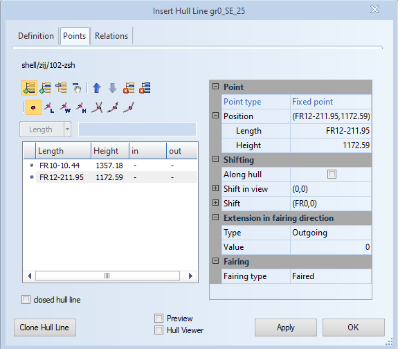
Point properties area
Allows browsing and editing the properties of a point. The properties are displayed as categories that can be hidden and shown by collapsing and expanding the categories.
Each category contains a list of properties with items for the selected point. The items displayed change with the point type. All edited fields are displayed in bold. If multiple objects have been selected, editing of the properties of all selected objects is allowed.
Point – Displays the type of the point, followed by its definition. For example, for a fixed point, the property Position will display the coordinates of the point in the active view as a summary and as a series of items. The position of the point is editable in both the summary (by introducing a value), as well as in the item fields (by introducing a value or by using the Up/Down buttons of the field).
Movement along relation – Displaces the position of the selected point with the introduced value along one of the relations that is used for the point definition. This category is only displayed for topological points.
Shifting – Displaces the position of a point, with the option to move along the hull shape. The resulting displacement can be a combination of a shift with respect to the X and Y coordinates of the graphical window, and a shift with respect to the ship coordinate system. The shifting for the latter is done in millimeters unless the value entered is a length value below 50. The coordinate that is not visible in the active view is not displayed. This is automatically assumed to be 0.
Dynamic Shifting – Displaces the position of a point along the tangent of the faired line at that point in the coordinate system of the active view. You can select whether to use the points' incoming or outgoing direction (note that only for Knuckles can these be different), and enter a distance value.
In case the outgoing direction is selected, the direction is rotated 180 degrees on the view, to interpret positive distance values as always extending a hull line. The distance must be given in the active unit system and if it is zero (0) then no shifting is done. Because the dynamic shifting depends on the points' directions, it is done after all other 2D shifts have been done, but before those 3D calculations that might also depend on directions (such as in-plane bending).
Fairing – Affects the direction of the hull line at the selected point by changing the fairing type. The fairing specifications support topological relations as well.