Symbols
Construction > Symbols/Dimensions > Symbols

Insert a hull line symbol or a weld symbol.
The Insert Symbols toolbar consists of 4 icons each representing a different symbol that can be inserted.
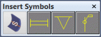
The first icon is for placing hull line symbols on hull lines in planar view, as they are defined in the hull line properties administration file. See Defining extra hull line properties for more information.
The other three icons are for placing weld symbols at a hull line or seam, with an optional accompanying weld code text.
The hull line icon/symbol is a permanent item in the toolbar; it cannot be replaced with another icon/symbol.
The other three icons/symbols are defined in the System Management application, Modify Icons function. See Modify Icons for more information.
Note: Although the weld symbol images are configurable, the behavior of the associated functions depend on the position of the icons/symbols in the toolbar, as follows.
| Icon | Symbol determined by | Indicates | Label options |
|---|---|---|---|
|
1st |
Selected line's properties |
Hull line in plane view |
No text |
|
2nd |
System management |
Weld in plane view |
Weld information text |
|
3rd |
System management |
Weld in cross section |
No text |
|
4th |
System management |
Block section weld |
Weld information text if not shell view |
Inserting weld symbols
Do the following:
-
Select the symbol to insert from the Insert Symbols toolbar.
-
In the case of Hull line symbols:
- In the graphical window, indicate the hull lines to get the plan view hull line symbol, as set for the hull line's type in the hull line properties administration file.
- If the indicated hull line has no symbol specified, or if the symbol is not found in the %ncgmodellen% directory, no symbol is added. This may happen either because the definition is missing, or because the line cannot be matched to a property set. An error notification is given in the message window.
In the case of Weld Symbols:
- Depending on the selected function (and current application), an extra Weld in View dialog may appear. Here you can set the weld code, which will be placed next to the symbol at the side where you selected the hull line (or seam). The three parts of the text will be combined into one weld code. The texts are set in System Management > Construction > Welds/Bevels > Weld Codes.
- In the graphical window, indicate the hull lines (or seams) to get the weld symbol.
-
Continue indicating hull lines (or seams) and inserting symbols as needed. In the case of weld symbols you can also change the weld code text parts.
-
Press the Esc key to stop inserting symbols.