Defining extra hull line properties
When coding the shell plates, the system can include marking lines, symbols and text for each hull line that intersects the shell plate.
There are three symbols that can be defined for the hull line and which will be displayed near the hull line (in cross section, plane and on production cutting data). You can apply these properties to groups of hull lines or to individual hull lines.
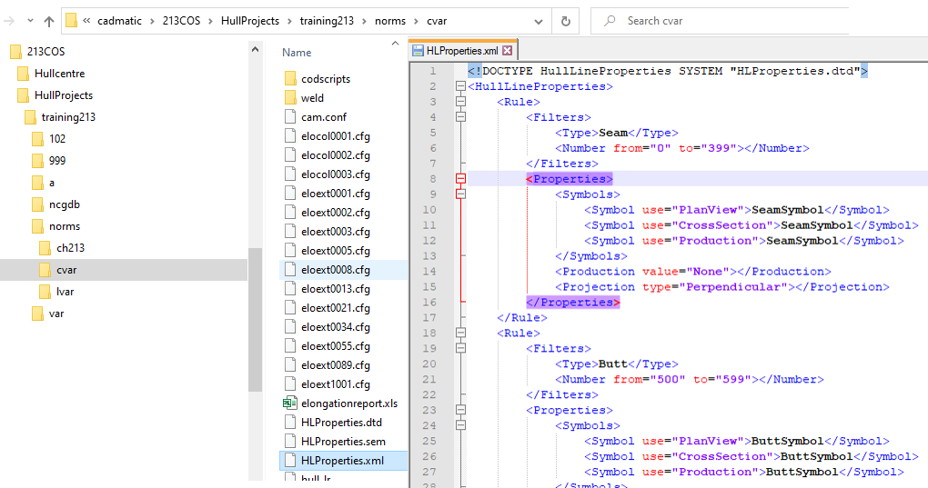
Extra hull line properties are defined in the HLProperties.xml file which is located in the project's norms folder, subfolder cvar. Open the HLProperties.xml file with a text editor to edit the rules for the extra hull line properties.
Note: If no extension is used, the system will automatically add the extensions: plv, crs, and prd.
See File structure of Hull Line Properties, Symbol, Production property, and Projection method for information on how to edit these properties according to your needs. In help topic Examples you can find some examples of correctly formulated rules.
Important: The view must be updated and/or recalculated, and the shell plates must be recalculated after the settings in HLProperties.xml are changed. If there is even one property, attribute or value that cannot be parsed by the system, the whole file will be considered invalid. In this case no properties are read.
The model files for the hull line symbols are located in the %ncgmodellen% folder of the active norms (mod2d by default).
Missing hull lines
If a hull line does not appear on a shell plate, check its properties and if its bounding box intersects the shell plate. These are the main reasons for hull lines not showing.
When the system encounters a hull line that results in an error during the projection of hull lines, it will simply skip it without notifying the user. Encountering such an error will not stop the coding process, as users usually prefer that the process is finished even if some hull lines are not present on the plates.
In cases where the system attempts to read the file but cannot locate it, is automatically creates a new HLProperties.xml file and fills it with the following default values:
|
Line key |
Line source |
[From, To] |
Symbol use= PlanView |
Symbol use= CrossSection |
Symbol use= Production |
Production |
Projection |
|---|---|---|---|---|---|---|---|
|
Seam |
All |
[300,399] |
SeamSymbol |
SeamSymbol |
SeamSymbol |
None |
Perpendicular |
|
Butt |
All |
[500,599] |
ButtSymbol |
ButtSymbol |
ButtSymbol |
None |
Perpendicular |
|
Dimension line |
All |
[400,499] |
DSSymbol |
DSSymbol |
DSSymbol |
Mark |
Inside |
|
Dimension line |
All |
[900,910] |
PaintSymbol |
PaintSymbol |
PaintSymbol |
Paint |
None |
|
Knuckle |
Other |
|
SeamSymbol |
SeamSymbol |
SeamSymbol |
None |
Perpendicular |
|
Angled curve |
Other |
[1,1] |
BaseSymbol |
BaseSymbol |
BaseSymbol |
BaseLine |
Perpendicular |
|
Angled curve |
Other |
[2,2] |
SideSymbol |
SideSymbol |
SideSymbol |
SideLine |
Perpendicular |
|
Angled curve |
Other |
|
AlSymbol |
AlSymbol |
AlSymbol |
Mark |
Perpendicular |
|
Function line |
Other |
|
FlSymbol |
FlSymbol |
FlSymbol |
Mark |
Perpendicular |
|
Any |
Other |
|
GeneralSymbol |
GeneralSymbol |
GeneralSymbol |
Mark |
Perpendicular |
When an extension has not been supplied for a symbol file name, the default one for its type will be appended (.plv for plan view, .crs for cross-section, .prd for production).
Important: The file name must not exceed 32 characters. Longer than 32 character file names will cause the parsing process to fail.