Setup Plotters
File > Plot Setup > Setup Plotters

With this function you can set up and configure printers/plotters by defining plotter properties. You can create new plotters, and modify and delete the existing ones.
It is possible to configure printers/plotters installed under Windows here, but it is not necessary to do so for them to appear in the Plot dialog. Windows devices can be directly accessed by the plotting functions.
You can also set up and configure Hull plotters. Once you have created a Hull plotter, it appears in the Plot dialog as a printer/plotter device.
For more information on the Plot dialog, see Plot.
Note: Plotters created with a Hull version earlier than version 2023T2 that use PDF (Portable Document Format) as the Output file format cannot use the pen colours defined in plotting configurations, but always print out as black and white. To enable the pen colours, save the plotter again in Hull version 2023T2 or later.
Plotter properties
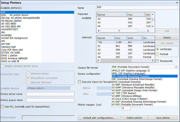
The following properties can be set for each plotter:
-
Name – Type in the name that is shown for the plotter in the Plot dialog's printer/plotter list.
-
Papersize – Select the paper sizes available for the plotter. The sizes are expressed in millimeters.
-
For Windows devices the available paper sizes are driver-dependent and cannot be changed.
-
For non-Windows devices sizes A0-A4 are always available. Other sizes must be defined in the device configuration file %eaglesite%\ncg.dcf in the Part2: PLOTTERS section, PAPERSIZE: setting, as custom sizes S1-S7.
The custom paper size settings are defined for each device configuration separately. Note that in the configuration file the sizes are expressed in centimeters.
Note: The maximum paper size for PDF is 508 x 508 cm (200 x 200 inches).
-
Once defined in the configuration file, the S1-S7 paper sizes will appear here as available paper size options for the selected Device Configuration, and they can be selected as paper sizes available for the plotter. A maximum of 10 paper sizes can be selected for a plotter.
-
-
Set default – The default paper size in the Plot dialog. The selected default size is indicated by an asterisk (*).
-
Landscape or Portrait. Paper orientation can be selected for each paper size once you have added it to the Selected field. With plotter macros, landscape is used if the orientation cannot be determined.
-
Rotation 90° – Gives a rotate command to the plotter. Enables saving paper in some cases when plotting on A1 size paper with an A0 plotter, for example.
-
Output file format (for connection types other than Windows device) – Several printer control languages are supported for physical printers/plotters, and for plotting to a file. Printer and plotter devices must support PCL5 page description language, or higher.
Note: Output formats that are generated by the ViewCompanion application do not support Windows fonts. Therefore, native Eagle font configurations must be used for those output formats. The output formats generated by ViewCompanion are indicated by a "VC" prefix, and include the following: VC-EMF, VC-WMF, VC-DWF, VC-TIFF, VC-BMP, VC-CALS, VC-DXF, VC-PDF.
-
Device Configuration (for connection types other than Windows device) – Select which configuration to use. The configurations are stored in the device configuration file %eaglesite%\ncg.dcf. The default value is PLOTHP, which is suitable for most cases.
-
Execute macro – Select a macro to be run before and/or after the plotting process. User-defined macros must be located in the %ncghelps% directory.
-
Plotter margins (cm) – Set the margin width for each side.
-
Disable standard plotter driver – If you need to use non-standard plot commands, disable the plotter driver, and define the plot commands in a macro. Select the macro in Execute macro.
-
Connection type – Select how to connect the plotter. To ensure full support of Unicode character set, select Windows device.
The following table sets out the properties for the other connection types than the Windows device.Connection type Device server name Device queue name Plot command Share system plotter lpnt \\system\plotter Direct connection n/a lpt1 lpnt lpt1 Network (IP/Host) system plotter lpr -S system -P plotter
lpnt copies the plot to the connected device. lpr uses the Line Printer Daemon protocol to send the plot to the connected device.
-
Use PCL (for connection types other than Windows device) – Adds extra (PCL) control codes to the plot file. Usually applicable only to laser printers.
-
Default plot configurations – Set default plot configurations for Enable/disable items, Pen replacement, Fonts, Pen thickness (on plotter), Pen thickness (in model), and Pen colours.
Note: Fonts in DXF/DWG output
Normally fonts are set in the Hull user interface. However, with DXF/DWG output, when Connection type is set to Share/Direct connection or Network (IP/Host), this is not the case. Instead, the fonts are defined in the file %ncghelps%\dxfplotfonts.dat. The Hull System Administrator must manually edit the file with a text editor to set the fonts in this case.