Shrinkage Compensation
Construction > Insert > Shrinkage Compensation

Add shrinkage compensation to shell plates manually. This function only works in 2D direction (aft, side, top, or perpendicular views).
Shrinkage compensation adds length to shell plates to compensate plate shrinkage caused by the welding process.
You can add compensation values in two directions, and set a rotation angle.
Note: The values set here override the values defined in the Production > Plate Cutting Data > Extra Length/Shrinkage setting in the System Management application.
See also Shrinkage compensation for shell plates in the Shell Plates Reference Guide.
Do the following:
-
Select the shell plate to which you want to apply the shrinkage compensation.
-
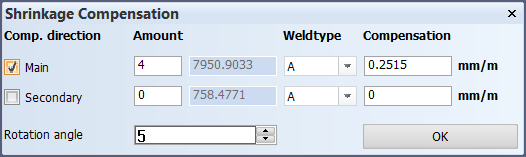
The Shrinkage Compensation dialog opens. The dialog shows the amount of shell frames connected to the shell plate in the main and secondary directions, and next to this the maximum distance of the two directions of the shell plate. These two values in combination with the weld type will calculate the compensation, which can be changed manually if so desired.
-
Change the properties of the shrinkage compensation as desired.
-
Comp. direction – The direction of compensation. You can select Main, Secondary, or both.
-
Amount shows the amount of shell frames connected to the shell plate in the main and secondary dimensions. If you want to exclude unimportant shell frames, enter the amount of shell frames (a lower value), and press Enter. the system re-calculates the default compensation value. The maximum distance of the two directions of the shell plate are shown next to Amount.
-
Weldtype – Select the desired weld type. If you change the weld type, the compensation is re-calculated.
-
Compensation – Shows the default compensation calculated by the system. This value is calculated based on the direction, the amount of shell frames, and the selected weld type. The value is given in mm/m per each shell frame on the shell plate. You can also enter the value manually. Press Enter to apply the new value.
-
Rotation angle – Rotate the angle between the main and secondary directions. The angle is presented as a vane symbol at the insertion point in the graphical window. Type in the value, and press Enter.
- This value must be between -90 and 90 degrees.
- A negative value rotates the vane clockwise, and a positive value rotates the vane counter-clockwise.
-
The vane is rotated according to the difference between the new and the previous rotation angle.
-
-
Click OK.
3D-Item Information
The rotation angle, and the main and the secondary directions are shown in the shell plate's 3D-item information.