Properties
Edit > Properties
View and modify the properties of selected 2D-items.
The properties of one or more 2D-items can be modified here, such as line styles and thicknesses, pen colours, text and dimension properties, and more.
This function can also be started by selecting a 2D-item and pressing the shortcut key I, as well as right clicking a 2D-item and selecting Properties.
The Selection toolbar gives you fast access to the selection filters that are used for interactive item selection: Select View > Toolbars > Selection.
See also Indicating items, Indicating points and Selection toolbar in the Basic Working Procedures User's Guide.
Item tree
The selected items are presented in a tree structure on the right side of the dialog. The drop down list at the top left defines the sorting criterion of the tree.
The default sorting criterion is Items, meaning that the selected items are organized by their item types. Eleven different item types are recognized (Arc, Circle, Dimension, etc.). Joined items and unknown items are placed in additional item types <Group> and <Other>, respectively.
Re-sort the tree as desired by selecting another criterion: Dash, Pen, Layer, or Thickness.
You can modify the contents of the fields that appear editable. Type in a new value in the desired field, and press Enter to apply it in the drawing.
Common properties
All the 2D-items have some common properties, such as dash pattern, layer, pen colour and thickness. Common properties are shown at the top right of the dialog.
Click an item in the tree to view its properties. If the tree selection contains more than one item, the property fields show their equal values. Property fields containing non-equal values appear cleared.
Item type specific properties
Each item type has its own set of specific properties. Item type specific properties are show below the common properties on the right side of the dialog. The item type specific properties appear once you have selected one particular item type in the tree.
Following is a list of the item types and their properties (click on the item type to see its properties).
An arc has a centre, starting, middle, and end points. You can move or align the selected arcs by changing their centre points.
An arc also has a radius and angle. You can type a new radius for the selected arcs, or use the plus + or minus - signs to increase or decrease the radius by a desired amount. After modifying the radius, the starting, middle, and end points are updated.
Convert the selected arcs into circles by entering an angle of 360 degrees. By modifying the angle, the middle and end points of the selected arcs are automatically changed.
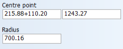
A circle has a centre point and a radius.
You can move or align the selected circles by modifying their centre point.
You can type in a new value, or use the plus + or minus - signs to increase or decrease the value by a desired amount.
Dimension text properties include Underlined, Boxed, Character height, Width/Height Ratio, Justification, and text Angle.
- Click Orientation to set the dimension text to the left, middle, or right of the dimension.
- Move the dimension text by clicking Reposition (not available if the orientation of the dimension text is outside the dimension). In case the arrow type of the selected dimension is not 3, 4, 6, or 8, repositioning automatically sets the arrow type to 3. This is to create more space for the dimension text.
The dimension arrow properties are Arrow size, Arrow type, show/hide Thickness line, and Thickness line direction.
- Change the placing point of a single selected dimension by clicking Adjust, and for rotating hole dimensions interactively.
- Align all the selected dimensions to another dimension by clicking Align, and indicating the dimension whose position to use.
An ellipse has by default the property of not being allowed to be split into smaller parts when it is involved with a clump or a conflict selection box. To break the selected ellipses into smaller parts by dragging a clump or a conflict box, select Allow to Split.
A line segment has a starting point, an end point, a length, and an angle.
Move or align the selected lines by modifying the starting point and/or the end point. Length and angle are recalculated according to the new point values.
Type in a new length or angle value, or increase/decrease these values by a certain amount by using the plus + or minus - signs. Modifying the length will also change the end point. By modifying the angle, the selected line(s) are rotated over their starting point.
Properties of a rectangle include:
- The coordinates of the lower left corner and the upper right corner (Point 1 and Point 2).
- The width and the height of the rectangle (Width and Height).
- The corner radius and the rotation angle (Radius and Angle).
You can increase or decrease the width, height, corner radius, and the rotation angle of the selected rectangle(s) by a certain value by using the plus + or minus - signs.
By typing in a new width, height, or angle, coordinates for Point 2 are recalculated. Select the Split to convert the selected rectangle(s) into line segments (and arcs, if the corner radius is not zero).
A spline is a curved line which is made of small line segments. The number of these line segments is shown in the Segments field.
Reference points are points which are indicated by the user when the spline is drawn. The number of reference points is shown in the References field. You can scroll through the reference points by using the left and right arrow buttons. The coordinates of the selected reference point are shown in the two Point fields. You can change the coordinates of the selected reference point.
A spline has a certain accuracy, which is shown in the Precision field. The precision of 1 means that between each two indicated reference points there is one point introduced by the system. The punctuality may be a value between 1 and 100.
By default the spline has the property of not being allowed to be split into smaller splines when it is involved with a clump or a conflict selection box. To break the selected spline(s) into smaller splines by dragging a clump or a conflict box, select Allow to Split.
File name shows the file name (and a part of the file path) of the selected sub-model.
The coordinates of the origin of the selected model is shown in the two Origin fields.
The enlargement factor and the rotation angle of the selected model are shown in the Enlargement factor and the Angle fields. You can type in a new enlargement factor or a new angle, or increase/decrease the existing values by using the plus + or minus - signs.
Text can be used for modifying the "Detail/Part Number" symbol text.
The pattern number of the selected surface(s) is show here.
Change the text or one of the text properties: Underlined, Boxed, Character height, Width/Height Ratio, Justification or text Angle. When the selected text has a link to a file, the file path is shown.
To use text contained in a text file, click the browse button, and select the file.
Click the parallel button to set the selected text parallel to the indicated line.
Click ![]() to resize the selected text interactively. After resizing, the character height and width/height ratio are automatically recalculated. The character height is rounded to one decimal point, and the width/height ratio is rounded to two decimal points.
to resize the selected text interactively. After resizing, the character height and width/height ratio are automatically recalculated. The character height is rounded to one decimal point, and the width/height ratio is rounded to two decimal points.
You can reposition the selected texts interactively by clicking ![]() , or by typing in the new position and pressing Enter.
, or by typing in the new position and pressing Enter.
You can change the text and click Apply Text to apply the changes.
To use contents of a text file for creating a TTF-text, browse for the file (the link to the file is not maintained).
Change the font styles to underlined, boxed, bold or italic.
Change the font face name by clicking Customize.
The TTF-text can also be created as line segments. Click ![]() .
.
Justification, Character height, Width/Height Ratio, and Angle can also be changed.
Accuracy defines the number of contour points. Accuracy can be a number between 1 and 10. Higher accuracy results in a smoother TTF-text, but also a bigger model.
To reposition the selected TTF-texts interactively, click ![]() .
.
The selected joined compounds are shown here.
All the selected items that do not belong to any of the item types described above are shown here.