Profile End Markings
Production > Plate Cutting Data > Marking > Profile End Markings
When a profile end touches a plate, it is possible to have this profile cross section marked on the DXF of the plate (regular plate or shell plate). The profile to be marked can be regular or bent, a pillar, bent pillar, pillar profile, or shell frame.
- Adding markings of the ends of bent pillars and bent profiles touching the plate can be useful for marking the placement of ladders, steps and grips, for example.
The profile end does not have to touch the plate exactly to get a marking. The maximum allowed distance between the coded part (plate) and the profile end can be defined by the Increase Calculation Thickness setting.
Profile angle to plate
The angle of the normal of the plate and the profile length direction in the touching end must be smaller than 70°, meaning that the angle between the profile and the plate plane should be more than 20°.
Markings
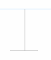
Only the molded side of the profile body (or bodies, in case of a H-bar), and the top side of the profile flange(s) are marked. Profile end cross section markings can have additional profile symbols, thickness indication, and angle markings, according to how they have been enabled and configured. Endcuts at profile ends are not shown in the markings.
The marking lines can be extended by a set length with the Body Marking Line Extension and Flange Marking Line Extension settings.
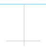
In case of user defined profiles, the system uses the weld line definitions in the type files to determine which lines to mark. Note that the weld lines do not usually touch (for example, the body weld line of a T-bar ends at the bottom of the flange). Therefore, horizontal and vertical weld line segments are extended to the profile section bounding box (grey lines in the picture below).
Settings
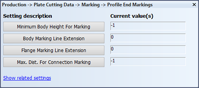
Minimum Body Height For Marking
To enable profile end marking, define the minimum body height for profiles that will get the marking.
A profile end marking will be added only for profiles that have a height bigger than or equal to the value set here.
The default value is -1, which means that this feature is disabled, and profile end cross sections are not marked at all.
Note: Shell frames can also be marked by enabling Production > Plate Cutting Data > Marking > Shell Frames > Shell Frame Markings. If you also enable profile end marking, by defining the Minimum Body Height For Marking here, shell frames smaller than the set minimum will be marked using the shell frame marking system, and other shell frames using the profile end marking system.
Body Marking Line Extension
Define how much the marking lines of the profile body are extended at both ends.
The default value is 0 (no extension).
Flange Marking Line Extension
Define how much the marking lines of the profile flange are extended. If the profile has two flanges, this setting applies to both flanges.
The default value is 0 (no extension).
The picture below shows an example with extensions of 25 mm.
Max. Dist For Connection Marking
Set the threshold value for drawing a connection line between pillar end markings or profile end markings.
When the distance between the markings is smaller than or equal to the value set here, the connection line will be drawn. If the distance is bigger than the set value, the connection line will not be drawn.
When the value is set to -1, this feature is disabled, and connection lines will never be drawn.