Settings
Production > Plate Cutting Data > Marking > Settings
Marking Side
With this setting the system manager can define on which side of the plate the markings should be placed.
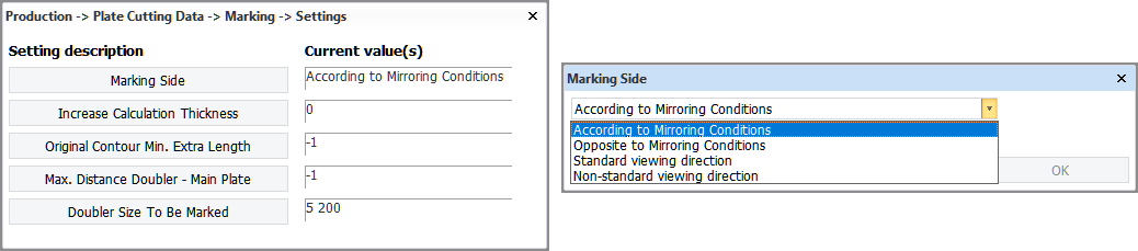
Select from the following options:
- According to Mirroring Conditions – The system will apply your pre-set settings in Production > Plate Cutting Data > Marking > Mirroring Conditions and mirror marking lines accordingly.
- Opposite to Mirroring Conditions – The system will apply the opposite of your pre-set settings in Production > Plate Cutting Data > Marking > Mirroring Conditions and mirror marking lines accordingly.
- Standard viewing direction – Marking lines only appear on the viewing side of the part.
- Non-standard viewing direction – Marking lines only appear on the non-viewing side of the part.
See Production > Plate Cutting Data > Marking > Lines for information on how marking side settings work in combination with different mirroring settings.
Increase Calculation Thickness
It is possible to have marking lines shown for the related parts on the coded plate, even if the other parts do not touch the plate to be coded. This setting defines the distance of the related parts to the plate to be coded, so that if the related parts are within this distance, they will be marked on the coded plate.
In a case where a longitudinal bulkhead is located at some distance below a deck (that is, not touching, so there is a distance between the deck plate and the bulkhead plate). By adding some 'calculation thickness', you can make the system include marking lines for the related parts. The actual thickness still remains the same. Adding calculation thickness makes the system consider the related parts in the coding process and include markings for them in the coded plate if the distance is within the setting value.
The related parts are marked on the plane of the plate. The default value of the Increase Calculation Thickness setting is 25 mm. This means that markings of related parts at or closer than 25 mm from the plate are included in the coded plate.
Calculation thickness to shell plates
It's useful to know that parallel distance is calculated in a different way than offset of shell plates. In case you want to add calculation thickness to a plate that almost touches a shell plate, you need to use the relation to the shell plate instead of the relation to the hull with parallel distance.
The image below shows how a relation with parallel distance (distance marked with red arrow) and how the offset of the shell plate is calculated (distance marked with green arrow).
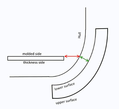
In case of a relation with parallel distance will be calculated by first obtaining the intersection of the plate's plane with the related item and then moving all points of this intersection in the same plane as the plate. On the other hand, a shell plate with offset is calculated by moving the surface of the hull along the direction of its normal.
This means that the plate will not necessarily be near to the shell plate if the offset and parallel distance are the same. Their deviation depends on the angle between the normals of the plate and the shape.
To make sure the plate has a specified distance from the shell plate, the plate must be related to the shell plate itself instead of the hull.
Original Contour Min. Extra Length
The original contour of the plate or shell plate can be marked with a marking line on the coded plate (DXF) when extra length is added to the plate or shell plate.
With this setting you can set the minimal extra length value that is considered for a marking. The coded plate will not get a marking if the extra length is smaller than the value set here.
The default value is -1, which disables the marking.
Note: If the extra length is negative, the original contour is not marked. The original contour will only be marked if the plate or shell plate becomes longer by adding extra length, and not when the plate becomes longer due to beveling.
The original contour markings are similar to reference line markings.
See also Extra length markings on the coded plate.
Max. Distance Doubler – Main Plate
Defines a condition for whether a doubler plate is to be marked on a coded plate (DXF) or not. A plate or bracket which runs parallel or almost parallel on top of another plate can be considered to be a doubler plate to the plate located below it. A doubler plate is welded onto the main plate to reinforce it. The main plate can be a deck plate for example. A deviation of max 3 degrees between the plate normals is allowed for the top plate to still be considered a doubler plate.
Also defines a condition for marking outfitting parts on a coded plate.
Markings for doubler plates
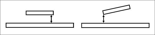
The setting value defines the maximum allowed distance between the doubler plate and the main plate. When the distance between the doubler plate and the main plate is bigger than the set value, there will be no marking of the doubler plate on the main plate DXF.
If the plates are not completely parallel, the distance is the shortest distance between them.
With the default value of −1 there will be no marking regardless of the distance.
Note that the Doubler Size To Be Marked setting below also controls whether doubler plates are marked on the coded plate or not.
See also Markings for doubler plates on coded plate.
Markings for outfitting parts
The setting value defines the maximum allowed distance between the outfitting part and the plate. When the distance between the outfitting part and the plate is bigger than the set value, there will be no marking for the outfitting part on the coded plate.
With the default value of −1 there will be no marking regardless of the distance.
With the value of 0 (zero), the outfitting part must be placed on the plate without any gap, or there will be no marking.
See also Markings for outfitting parts on coded plate.
Doubler Size To Be Marked
Defines a condition for whether a doubler plate is to be marked on a coded plate (DXF) or not. A plate or bracket which runs parallel or almost parallel on top of another plate can be considered to be a doubler plate to the plate located below it. A doubler plate is welded onto the main plate to reinforce it. The main plate can be a deck plate for example. A deviation of max 3 degrees between the plate normals is allowed for the top plate to still be considered a doubler plate.
The setting value defines the range of the allowed length and width for the doubler plate to be marked on the coded plate. Both the length and the width of the doubler plate must fall within this range or it will not be marked.
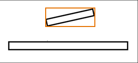
If the doubler plate is not exactly parallel to the main plate, or has an irregular shape, the size of the doubler plate is considered to be the size of the smallest rectangle around it. The contour of the doubler plate is projected onto the main plate by simply "dropping" the contour onto the plate.
Note: The Max. Distance Doubler – Main Plate setting above also controls whether doubler plates are marked on the coded plate or not.
Note: Also the Brackets settings Bracket Length For Markings and Markings For Brackets affect whether a doubler bracket is marked on the plate or not.