Settings
Production > Plate Cutting Data > Orientation Axes > Settings
Orientation Axes
Parts can be given a reference coordinate system that indicates how they are positioned within the ship. The coordinate system has two orientation axes that define two directions that are dependent on the part type. An orientation axes symbol indicating the directions is placed on the coded part.

Note: When two or more plates are combined using a knuckle attribute, the orientation of the original part that gets the part number is used to determine the orientation of the total part, and that original part will also get the orientation axes symbol.
This setting consists of five parameters. Each parameter has its own input field.
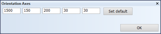
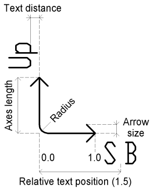
The five parameters are as follows. From left to right:
- Margin: Parts with a smaller diagonal than the value set here are not given coordinate systems. This prevents the assignment of coordinate systems to small parts such as brackets. The term 'uit' (the default) disables the setting.
- Displacement of the origin of the coordinate system with respect to the bottom left corner. This parameter can be used to set the distance from the coordinate system to the contour edge.
- The length of the axes.
- The radius of the arc between the two axes. The default is 0, which means no radius. This is an optional parameter. If you set parameter 5, you must also set this one.
- Sets the size of the arrowheads. The default is 10. A value of 0 means no arrowheads. This is an optional parameter. If you set this parameter, you must also set parameter 4.
The position of texts along the axes is set as part of the Position and Dimension settings. See Orientation Axes Text.