Report Layout
Production > Profile List > Report Layout
Production > Profile Nesting List > Report Layout
Production > Shellframe Bending List > Report Layout
Production > Hole List > Report Layout
Production > Profile List Sketch > Report Layout

The purpose of CADMATIC Hull is the creation of construction items. A combination of geometrical and logistical data for these constructions can be represented in reports.
Reports use so-called IND files. Each IND file determines the layout and content of the report and specifies the geometrical and/or logistical information that should be included in the report to be generated.
Use the above functions to create report layouts. A layout has four parts that can be created by clicking the corresponding buttons in the Report Layout dialog.
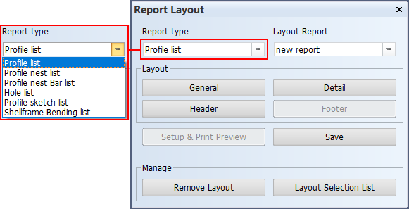
Report type
Of the several report types that are present, each type has his own purpose, and can be used only for that purpose. The table below explains each type.
|
Report type |
Explanation |
|---|---|
|
Profile list |
A list that contains all the product information for each non-bent profile, with the exception of the bent faceplate. The list is sorted by profile type and part number (in ascending order). It normally shows the assembly lines, so that the user will know where the profile is located in the ship. A "recognition word" (one or more characters long) may be added for identification of the profiles for which a profile sketch should be made. |
|
Profile nesting list |
A list in which all profiles are classified according to predefined bar lengths. It also creates a file in which the required number of bars is given. The program also makes use of various settings to determine the bar length for each profile type and the thickness of the cutting. |
|
Profile bending list |
A list that contains bent shell frames. |
|
Hole list |
A list that contains the position, description, and status of the hole. The list can be used to obtain an overview of the holes generated with the Plant Modeller module. It also gives the user the option to accept these holes or change their status. |
|
Profile sketch list |
The system supports two kinds of sketches. The "Profile sketch" type represents the exact shape including holes, cutouts ,and bent information of each profile. The "Profile sketch list" type presents a series of profiles with the same end types in one sketch. In this case the sketch is a presentation of several profile without the presentation of holes, cutouts and bent information. |
Layout Report
Select one of the predefined report layouts.
General settings for report
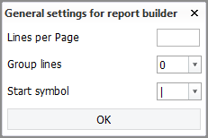
- Lines per Page – Enter the number of lines after which a new page should begin. The number includes the lines of the header, footer, and any extra space between lines. This setting should match the page length for the selected printer.
- Group lines – Set the number of lines after which extra space (a blank line) should be inserted. If no extra space should be added, enter 0. No start or end symbols will be placed in these blank lines.
- Start symbol – Set the symbol to be placed at the end of each line.
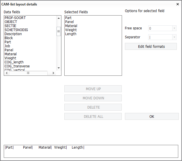
Report layout details
Specify the report layout details, such as the columns, and which items should be placed at which positions in the report, and how the items should be displayed.
Header
Specify the layout of the report header. The header is shown at the top of each page in the report.
Footer
Specify the layout of the report footer. The footer is shown at the bottom of each page or, if subsummaries are used, after each subsummary.
Saving the report layout
Each report layout must be saved before it can be used. If the report layout has been changed, the name of the report layout will be entered automatically in the Layout Name entry box of the Save Layout dialog. You can change the name before saving the layout. An existing name can also be selected from the Available Layouts list. This name will then be entered in the entry box automatically.