Bending Lines
Production > Plate Cutting Data > Templates > Shell Plates > Bending Lines
Bending lines are markings on a separate DXF file that shows how templates are positioned on the shell plate. Settings for bending lines help in creating a clear DXF file that is easy to use at the production site.
See also Bending lines in the Shell Plates Reference Guide.
DXF File Name
This setting can be used to create a unique DXF file name for all DXF files with bending lines. The generated DXF file is stored in the ../project/block/pi folder.
Extension
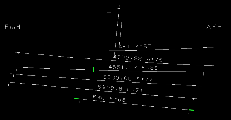
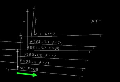
Lines can be extended in the DXF file: both the bending lines that indicate where the template touches the shell plate and the lines that indicate where the templates intersect the sight line plane. The starting point of extensions are marked by crossing marks. With this setting you define the length of the extension.
The image below shows the extensions highlighted with green.
Crossing Marks
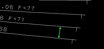
Define the length of the crossing marks. Crossing marks indicate the end of the bending lines and the points where each template intersects the sight line plane. The image below shows the crossing marks highlighted with green.
Spacing Distance
Set the minimum distance in mm between the template bending lines in the drawing.
-
The first bending line is added upright at (0, 0).
-
The lines are added sequentially.
-
Spacing vector is added to the last origin.
-
Fitting parameters are computed, that is, the angle range.
-
If the range is empty or the angle with the smallest difference between min and max distance is more than double the min, the spacing vector is multiplied by square root of 2 and fitting is retried.
-
-
The total distance is calculated by adding together all distance vectors.
Note: The process is repeated in reverse order for templates and the layout with the smallest total distance is chosen.
The purpose of reversing the order is to minimize the dimensions of the resulting DXF drawing. This is done by trying to minimize the distance between the positions of the lower and upper line.
Depending on the shape of the lines, the distance is usually different when piling the templates in reverse order. That is, starting by placing the last template at the bottom and then adding the previous template, until the first one. Since each line is shifted and rotated until the required tmplsetspacing distance (minimal acceptable distance between each two lines) is met, the results will differ not only in their order.
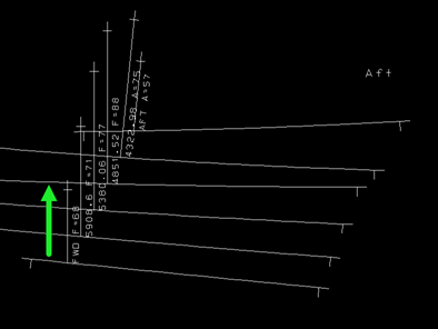
The direction of the line along which the templates are positioned is usually a line with a 60 degree inclination (the red arrow in the figure below).
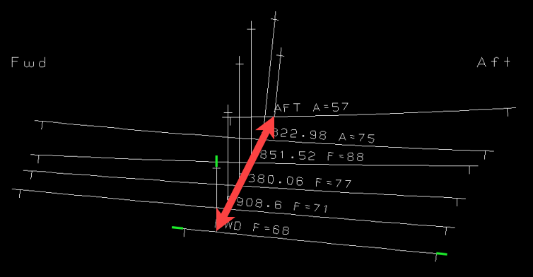
However, the distance between the points on this line where the templates are positioned is not necessarily tmplsetspacing, but at least tmplsetspacing. The distance on this sloped line might be increased in order to have two consecutive bend lines not closer than tmplsetspacing apart (on any position along the lines).
Bounding Box
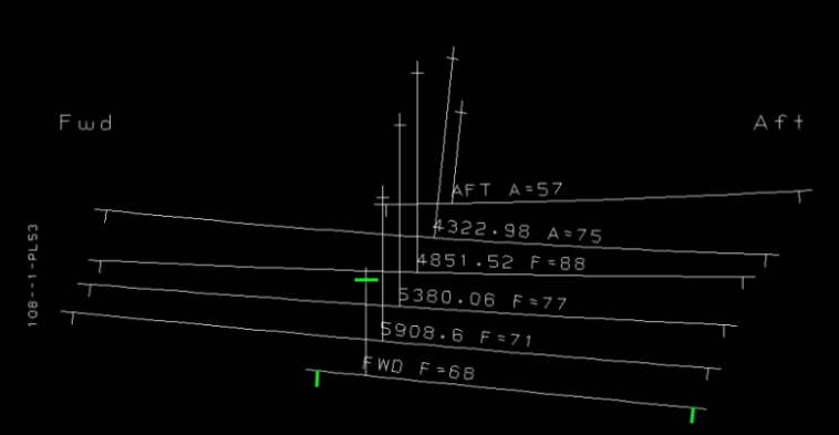
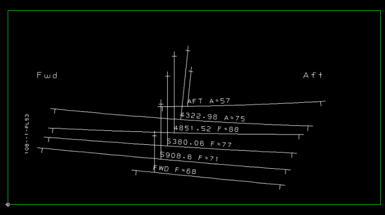
Enable or disable the bounding rectangle around the drawing. By default the option is disabled. The image below shows an example where the bounding box is enabled.
Template Text Alignment
Change the alignment of the template text on the bending lines. Select from the following two options:
- Align text using shell plate (default) – Template text is aligned horizontally in the direction of bending line. See image below:
- Align text using sight line plane – Template text is aligned vertically in the sight line intersection direction. See image below: