Bending lines
The user can create a separate DXF file that shows how templates are positioned on the shell plate. The DXF file with the so called bending lines can be used by production to position the templates accurately on the shell plate during the bend process.
This DXF file includes information about:
- the position of the templates (for example the frame number at which the template is positioned)
- the orientation of the templates
- side and baseline information.
Follow the steps below to generate a DXF for all templates belonging to a shell plate:
- Go to the Template tab in the Shell application. Create a new template set by clicking New, proceeding with the template creating steps and saving the templates, or open a template set by clicking Open.
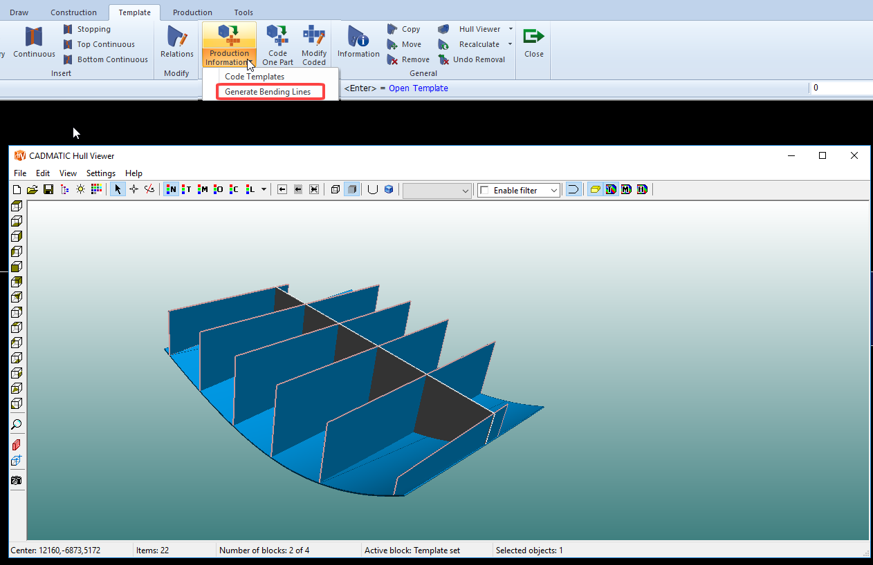
- Select Production Information > Generate Bending Lines in the Production section of the Template tab.
- The generated DXF is displayed in the view. The system shows the location of the DXF file in the message window.
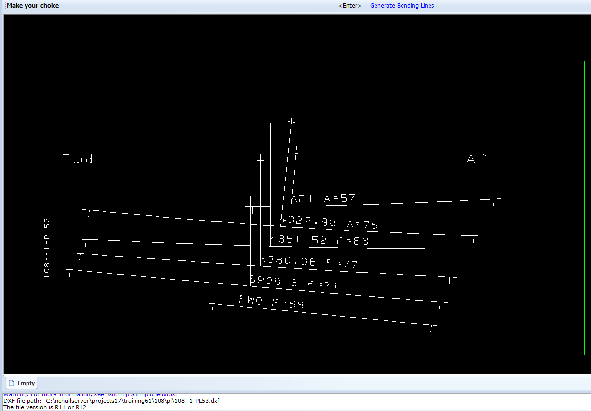
Abbreviations A (Aft) and F (Fwd) in the drawing mark the angle (in degrees) between the template and the shell plate, measured in the plane of the sight line plane. The prefix (A or F) indicates the side of the smaller angle.
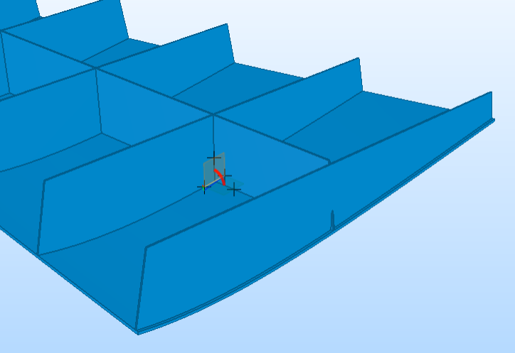
The location of the angle between the template and the shell plate:
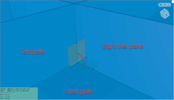
Details of the angle between the template and the shell plate in the sight line plane:
Relevant settings in the System Management
Go to System Management > Production > Plate Cutting Data > Shell Plates > Orientation Text to change the orientation text on the DXF data.
Go to System Management > Production > Plate Cutting Data > Templates > Shell Plates > Bending Lines to change the following settings:
- the file name of the DXF
- length of the extensions to the bending lines
- length of the crossing marks that mark the end of the bending lines
- minimal spacing distance between the bending lines
- displaying or hiding the bounding box
- changing alignment of the template text.