User Defined Profiles
Construction > Profiles > User Defined Profiles
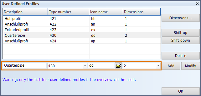
In addition to using the default available profiles, it is possible to use user-defined profiles. Here you can define new user-defined profiles and modify existing ones.
The following properties can be defined for profiles:
-
Description – The text that is displayed when creating or modifying the profile, up to a maximum of 40 characters.
-
Type number – The type number for the profile, this must be a unique number within the range [421...448]. Select the desired type from the list.
-
Icon name – The name of the bitmap icon (without the file name extension .bmp) that is used in the profile creation and modification functions. The name consists of two characters, and it cannot be any of the following reserved names: ST, HP, HG, HO, RD, PY, HR, VK, TB, HB, KO, UP, DS, IH, HA, PU, HI, IP, AS, UN, FB, HM, IE.
The 2D-Contek, 3D-Contek and 3D-Show applications have different locations for the icon files. The icons are located in the project's norms folder, as follows:
-
profs2d for 2D-Contek
-
profs for 3D-Contek
-
profs3d for 3D-Show
Dimensions – Sets the amount of dimensions required for the definition of the profile. Click Dimensions to define the available dimension values for the selected profile type. This list is located in the directory %ncgnorms%\dimension, and the file name is defined by the icon name: <icon name>modellen.inp.
- Although both the metric and imperial unit system are supported in the dimension settings, it is recommended to enter the dimensions in only one unit system for a specific profile type.
- By default, all profile dimensions are displayed in the unit system set for the project.
- Dimensions for profile types set in the Construction > Profiles > Dimension Unit System function will always be displayed in the unit system defined for that profile type, overriding the default behavior.
Note: Only four user-defined profiles in can be used at the same time. If more than four profiles are defined, the four topmost profiles in the list will be available. Use Shift up and Shift down to move profiles up and down the list as necessary.
Defining a new user defined profile
Do the following:
-
Fill in the fields at the bottom of the User Defined Profiles dialog:
-
Enter a description (name) for the profile.
-
Select a type number for the profile from the drop-down list. You cannot use a type number already in use.
-
Define the icon name. Click
 to browse for the icon file, or enter the icon file name (without the file name extension). Note that the icon file must be located in the profs folder in the project's norms folder (for 3D-Contek).
 -
Select the number of dimensions from the drop-down list.
-
-
Click Add. The system adds the new profile to the list.
Because only the top 4 profiles on the list can be used, you may need to move the new profile up by clicking Shift up. -
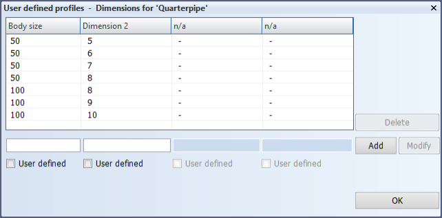
Click Dimensions to open a dialog where you define the dimensions that users select from when inserting the profile into a drawing.
-
Enter the dimensions as value pairs. Once you have entered all the desired value pairs, click Add to insert the dimensions into the list.
-
Body size defines a profile body size.
-
Dimension 2 defines a body thickness.
Selecting User defined allows the users to enter the dimensions freely.
-
-
Click OK. The user-defined profile is now created.
Important: You must add the newly created profile as a new line to the profile list in System Management > Logistics > Prefixes And Part Codes. In the Prefixes And Part Codes, the profile appears in the Construction part drop-down list and can be selected from there. Enter abbreviations for the profile in Report & sketch and Robot profile type, for example QQ for both in the case of the example above. Optionally you can define a part code for the profile as well.