Automatic panel numbering of parts
The Automatic Part Numbering function assigns each part a unique identification number that consists of a panel number, sublevel and a part number.
- The panel number is a collection of assembled construction parts (plates and profiles, with brackets and lugs) which are situated in the same plane or are connected to this plane.
- A plate with its related profiles will get a unique sublevel.
- The part number is a unique number within this collection or within the entire block.
Automatic part numbering consists of the following two steps:
-
Define the plane and the panel name. All names can be modified manually later.
-
Process the sublevel and the part.
This Help topic explains the first step: how to define the plane and panel name. The automatic part numbering process is described in Automatic part numbering within panels.
Plane name
A panel is a group of parts and sub-assemblies, mostly belonging to one assembly step. The plane name is used to group parts belonging to one plane with a certain margin in depth. A plane is one level in the entire block. A plane could be a frame, for example.
The plane name is used to control the panel groups. It is possible to insert a start name/number which is used as the first plane name instead of the average plane position. The plane name can be useful as a branch within the work breakdown tree.
The constructions positioned within the same plane get a unique plane name. This name is normally the frame number or height or breadth of the plane, if the plate is slanted the average plane level will be used. When the user defines a name or number in the input field of the Plane name, this name or number will be used for the first plane. The next plane (in order of the levels) gets the next number in succession until every plane is numbered.
The plane name is always preceded by a prefix that specifies the orthogonal plane (length, breadth, height). By default, values L (for length), B, (for breadth) and H (for height) will be used. The prefixes can be changed with the Plane Name Prefix settings in System Management > Logistics > Partnumbering > Other.
If no plane name has been entered, the system will create the plane name in the following ways:
- The plane name of a part with a fixed length value will be the frame number, if necessary supplemented with a value for the frame in millimeters for parts that are not entirely mounted on the frame. For example: FR100, FR104+200, and so on. Note that the default is not FR but L.
- The plane name of a part with a fixed breadth or width will be the Height or breadth value. For example: H4200, H12300 or B12300, B-5300, and so on.
If the user enters a value (number or sequence of letters) in the Plane name entry field, all parts situated in one plane will be given this unique plane name. With a user-defined prefix all parts will get the same prefix, so there is no distinction between them based on the plane direction. The plane name prefix will always be added.
Two margins will be used to define the plane positions. The Plane Layer Margin and Slanting Plane Layer Margin in the System Management application.
Note: The plane name for foundations will never be changed by the numbering system, so these parts will be treated as one branch.
Panel name
There are three methods to define the panel name. These will be described here one by one:
The first method is meant to give each part a unique panel name. The definition of a part is a plate construction which is made with function Create plate.
Note: Parts in a plate get the same panel name when this plate construction has one or more seams.
The second method is meant to give all parts within the same plane the same panel name.
The third method is meant to give all parts within the same grid level the same panel name. Specified, not by the given name in the input field of the automatic part number panel, but by the grid definition. Because of the fact that a grid has an orthogonal plane, slanted plates will get the same name as the plane name.
The first and second methods are used when the system management setting Panel numbering system is set to Whole ship. The third method is used when it is set to Area.
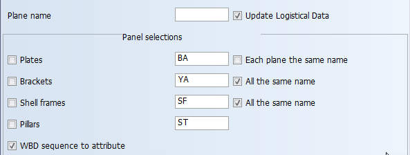
When using the first or second method, the range of the panel number can be set separately for plates, brackets, shell frames, pillars, and foundations.
The start panel names are not shown in the user interface when the third method is used, the dialog below is only valid for the first and the second method.
The part numbering system expects that the sublevel is not a part of the work breakdown tree when the first or second method is used. That is why this option is not visible in the user interface when these methods are used.
For more information, see Automatic part numbering within panels.
Brackets, shell frames and pillars
It is possible to give the brackets and shell frames the same panel, while all pillars will get the same name.