DXF Parts to Sketch
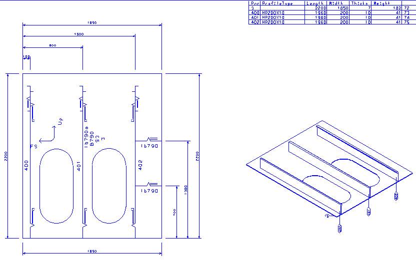
With the DXF Parts to Sketch function you can generate measurement sketches in combination with the 3D work breakdown sketch according to the work breakdown structure of the attached 2D part. This function provides a sketch for each DXF part that is greater than a specified size. First you must specify a configuration for the sketch layout and data types.
Select Production > DXF Parts to Sketch to open the function.
In general, the DXF Parts to Sketch function works as follows. Once you have selected some or all parts, the system makes a measurement sketch for each part. The parts that are smaller than the value specified in the Skip parts smaller than setting will be skipped. The type of measurement and report style can be selected in the Settings tab. In case the 3D sketch is present and requested in the layout of the sketch, it will be visible.
The sketch can be loaded into a sheet drawing using the Insert function in the sheet drawing environment. Click WBD Selection to see the available sketches.
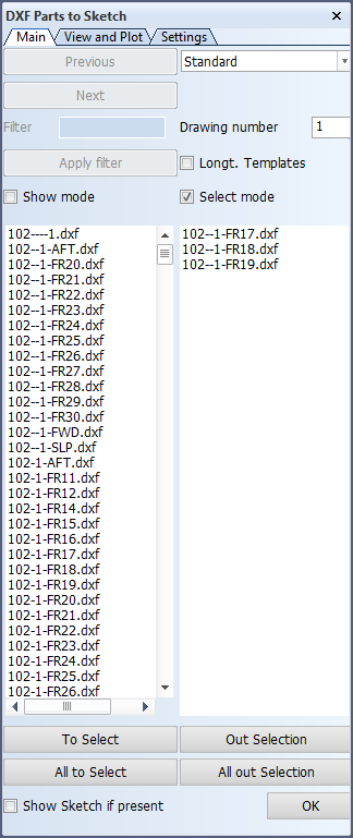
Main tab
The Main tab is used to select or get a preview of the part.
Available functions and options:
-
Previous and Next – Click to see the previous or the next part in the list.
-
Filter – Enter a character string to filter the parts to be shown. If the character string is present in the DXF file name, only these parts are shown in the list after clicking Apply filter.
-
Show mode – The part is displayed in the graphical window after selection. In this mode, the part can be moved in or out of the selection list by clicking To Select or Out Selection.
-
Select mode – One or more parts can be selected by the normal window selection rules and can be moved in or out of the selection list by clicking To Select or Out Selection.
-
All to select – Move all parts in the list on the left pane to the selected parts. Filter can help you specify a specific selection in this list.
-
All out Selection – Deselect all parts.
-
Show Sketch if present – This function will display the total sketch if it is present.
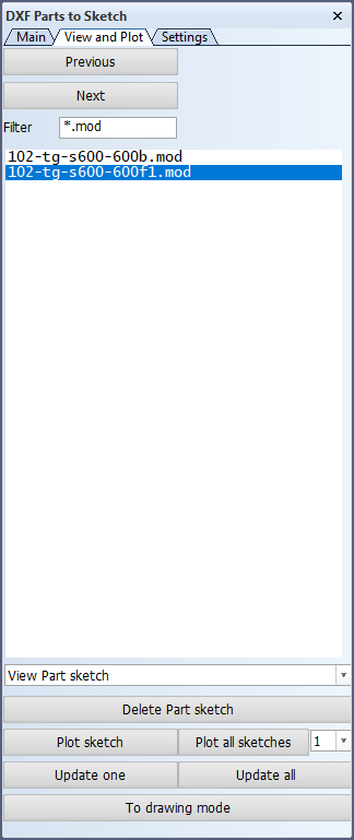
View and Plot tab
The generated sketches can be viewed and plotted or updated to the last changes of the 2D part in the View and Plot tab.
In the drop-down menu after the list pane the following functions can be selected:
-
View Part sketch – Show the selected sketch in the graphical window.
-
Delete ALL Part sketches – Delete all sketches from the list. Filter can help you specify a specific selection in this list.
-
Cancel – Cancel the view and delete actions just made.
Other functions:
-
Delete Part sketch – Delete the selected sketches from the list.
-
Plot sketch and Plot all sketches – Plot the selected sketches, or all sketches.
-
Update one and Update all – Update the selected sketches or all sketches to the last generated DXF and, if requested, the 3D sketch. Filter can help you specify a specific selection in this list.
-
To drawing mode – Hide the DXF Parts to Sketch dialog temporarily. You can then use the normal 2D drawing options to change the part. Using Save or restarting the Production > DXF Parts to Sketch function will again show the dialog and save the changes. Closing the dialog prevents anything from being changed.
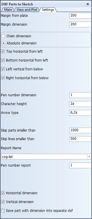
Settings tab
The preview is controlled with the settings in the Settings tab. You can define how the part is shown in the graphical window and in the sketch, control the measurement method and the type of dimensions placed around the DXF part.
After changing any of these settings, the new settings will be used as default the next time the function is started.
Available settings:
-
Margin from plate – Set the minimum distance between the part and the first dimension.
-
Margin dimension – Set the minimum distance between the dimensions.
-
Chain dimension or Absolute dimension – Select the dimension method. When Absolute dimension is selected, the following options can be selected.
-
Top horizontal from left – The dimension located at top of the part will have its orientation from the minimum left side of the part. If switched off, it will have its position from the right.
-
Bottom horizontal from left – The dimension located at the bottom of the part will have its orientation from the minimum left side of the part. If switched off, it will have its position from the right.
-
Left vertical from below – The dimension located at the left side of the part will have its orientation from the lowest side of the part. If switched off, it will have its position from the top side.
-
Right vertical from below – The dimension located at the right side of the part will have its orientation from the lowest side of the part. If switched off, it will have its position from the top side.
-
-
Pen number dimension – Set the pen number used to draw the dimension.
-
Character height – Set the character height used to draw the dimension. Character a must be addedafter the height value to fix the height to the plot scale.
-
Arrow type – Several arrow types can be used. The value consists of the arrow type number followed by the height of the arrow.
For example, 6,2a, where 6 is the arrow type and 2a is the height of the arrow in relation with the scale of the drawing. If only 2 without the following a , the arrow height will not be related to the plot scale, but will have the height of 2 mm related to the real 1:1 size of the drawing.
-
Skip parts smaller than – Parts with a smaller size will be skipped from this function, no sketch will be made.
-
Skip lines smaller than – Lines with a smaller size will get no dimension.
-
Report Name – A report layout can be selected from this drop-down list to be drawn on the sketch, see Production > Part Sketch > Sketch Layout in the System Management application to define the position of the corners of the report on the sketch layout.
-
Pen number report – This defines the pen number with which the report will be drawn to the sketch.
-
Horizontal dimension – When selected, horizontal dimensions are shown in the sketch. When cleared, horizontal dimensions are not shown.
-
Vertical dimension – When selected, vertical dimensions are shown in the sketch. When cleared, vertical dimensions are not shown.
-
Save part with dimension into separate dxf – It is possible to use the dimension even in Nestix. For this reason it is possible to save the DXF part with dimension to a special folder. The folder will be named dxfsketch and it will be located in the folder where the DXF parts are saved.
For more information on the above mentioned settings, see Production > Part Sketch > Settings in the System Management application.