Angle indicator symbol
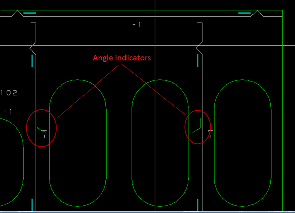
Angle indicators show the angle in which another construction part touches the coded plate.
The angle indicator consists of two short lines that form an angle opening that is equal to the obtuse angle between the parts.
The angle indicator is placed near the marking line of the part that touches the coded plate, between grid lines near the center of the marking line, on the side of the marking line where the obtuse angle is.
- Angle indicators are shown for obtuse angles only (angles between 90 and 180 degrees).
- An angle indicator is not displayed if the other part is perpendicular to the coded plate.
- An angle marking that would be positioned in a hole will not be shown.
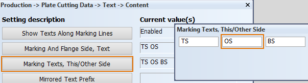
In cases where the connected part is on the other side of the plate, a text label indicating this is placed on the angle indicator marking. The content of the text label is the abbreviation that has been set to indicate the other side in markings: Production > Plate Cutting Data > Text > Content > Marking Texts, This/Other Side setting, in the System Management application.
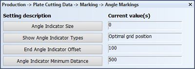
The size of the angle indicator can be set using the Angle Indicator Size setting in the System Management application, Production > Plate Cutting Data > Marking > Angle Markings.
The value sets the length of each line that forms the angle indicator. If the value is set to zero, the angle indication will not be present on the DXF file. To have the angle indication present on the DXF file you must define a positive value.
Angle indicators for curved constructions
For situations where the angle changes because of curved constructions, it is possible to show additional angle indicators (end markings) at the extremities of the part touching the plate.
The image below shows an example of a curved construction, where a shell frame is placed on a shell plate (on the left). The angle between the shell frame and the shell plate varies along the shape.
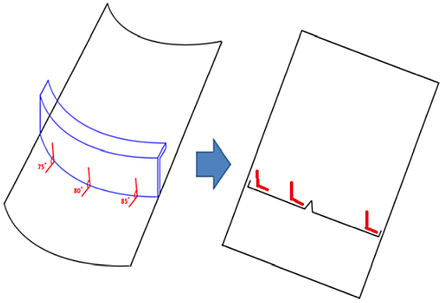
Additional angle indicators can be placed at the extremities of the part touching the plate, as shown on the right.
The following Angle Markings settings are available for defining how angle indicators are presented on the DXF file:
- Show Angle Indicator Types: Define which angle indicators are shown.
- End Angle Indicator Offset: Set the distance between the end angle indicator and the part end.
- Angle Indicator Minimum Distance: Set the minimum distance between the center and end angle indicators.
In cases where the extremities of the part touching the plate are located outside the plate, only the center angle indicator is shown.