Bending information for shell frames and face plates
Bending lines can be included in shell frame and face plate DXF files. To do this, you need to add keywords for the bending information to the dxfrobot.ind file. This robot file controls the profile DXF output.
Keywords in dxfrobot.ind for shell frames
When set to Handle all as straight in the System Management setting in Production > Plate Cutting Data > Shell Frames > Code Shellframes, the bending lines are included in the shell frame sketch and DXF file, and the text used to indicate the part of the face plate to be bent. See Shell Frames.
Add the following line to the dxfrobot.ind file:
I,B;NC-PARAMETERS> 913,1,$XBS,1,1,1,1,1,1,1,1,1,0,$YBS,$AMPLITUDE,$XBE,$YBE,0,0,0,0,0,0,0,0,0,0,0,0,0
This line adds the content of type file 913 to the .dxf contour of shell frame. Type file 913 contains information that is needed for the correct bending line placement. Type file 913 is located in the default norms.
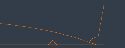
The bending line will be shown in the sketch.
Keywords in dxfrobot.ind for face plates
The System Management settings in Production > Profile Sketch > Face Plates define whether a face plate is handled as a knuckle or as a radius, whether the face plate radius information is shown in the profile sketch and DXF file, and the text used to indicate the part of the face plate to be bent. See Face Plates.
Add the following lines to the dxfrobot.ind file:
I,DXF;NC-PARAMETERS> 503,$FACE_PL_BEND5_LENGTH,40,50,40,$BASIS,40,50,40,DN$FACE_PL_BEND_ANGLEFIN/R$FACE_PL_BEND_RADIUS
I,DXF;NC-PARAMETERS> 503,$FACE_PL_BEND3_LENGTH,80,0,80,$BASIS,80,0,80,$FACE_PL_BEND_ANGLE,0,TAN
I,DXF;NC-PARAMETERS> 908,1,$FACE_PL_BEND1_LENGTH,0,0,0,0,0,$LIJFHOOGTE,1,0,0,0,20,0,0,0,0,0,0,0,0,0,0,0,0
I,DXF;NC-PARAMETERS> 908,1,$FACE_PL_BEND2_LENGTH,0,0,0,0,0,$LIJFHOOGTE,1,0,0,0,20,0,0,0,0,0,0,0,0,0,0,0,0
I,DXF;NC-PARAMETERS> 503,$FACE_PL_BEND5_LENGTH,80,0,80,$BASIS,80,0,80,$FACE_PL_BEND5_LENGTH,0,TAN
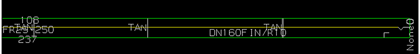
Defined in the first line above, DN$FACE_PL_BEND_ANGLEFIN/R$FACE_PL_BEND_RADIUS will show the bend angle and the bend radius of the knuckle.
"TAN" will be shown in the place of a knuckle without radius.
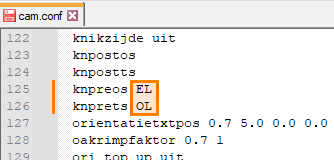
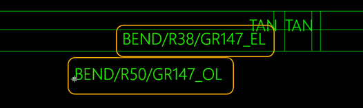
Optionally, keyword $FACE_PL_BEND_ANGLE_SIGN can be used for knuckle direction indication. In that case the cam.conf file in the norms must be updated. Keywords knpreos (knuckle indication this side) and knprets (knuckle indication other side) must be given values EL and OL, respectively.