Face plates in profile sketches
The profile sketch settings for face plates are defined in System Management > Production > Profile Sketch > Face Plates. See Face Plates.
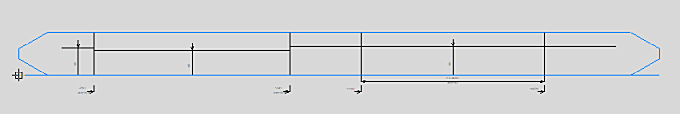
In cases where a face plate is on multiple plates, all the related plates are marked in the profile sketch. Each plate's marking in the sketch shows the upper side of the plate against the face plate. Each plate's marking line is always straight.
In Hull version 2019T2 or older, you must add four new keywords to the robot layout file ncgrobot.ind in the norms folder of the project (%ncgnorms%) to have all the plates marked in the sketch. Otherwise only the main plate is shown.
The new keywords must be defined in the HAF part of the file. The HAF part is handled for all plates to which a face plate is related.
HAF,$CENTER_DISTANCE,$PLATESTART,$DISTANCESTART,$PLATEEND,$DISTANCEEND
Others than $CENTER_DISTANCE are the new keywords. If the new keywords are not used in the layout file, the keyword $CENTER_DISTANCE is still used.
- $CENTER_DISTANCE is the distance of the main plate to the base line of the face plate.
- $PLATESTART is the length position in sketch of the start of a related plate.
- $DISTANCESTART is the distance of a plate at its start to the base line of the face plate.
- $PLATEEND is the length position in sketch of the end of a related plate.
- $DISTANCEEND is the distance of a plate at its end to the base line of the face plate.
Length positions are relative to the left bottom corner. The start and end do not need to be at the exact length position, but the distance must fit exactly at the length position.
An extra condition is that the relation has some length.
If a face plate is a bulb or an angle bar, and it has non-standard thickness direction, the flange line in the profile sketch is presented as follows:
- When looking from the plate to the face plate, the flange line is solid.
- When looking from the outside towards the plate, the flange line is dashed
Face plate rotation angle
Rotation angle information can be included in the profiles sketch by adding the Plate to face plate angle field to the sketch layout. See the Sketch Layout dialog section in the System Management > Production > Profile Sketch > Sketch Layout topic in the Help.
The Plate to face plate angle field is available for the sketch layout when the following variable/keyword is present in the %ncgnorms%\ncgrobot.ind file: PLATE_TO_FACEPLATE_ANGLE, [keyword]. The keyword defines how the face plate's angle to the related plate is expressed in the sketch. The following keywords can be used:
- $PLATE_TO_FACEPLATE_ANGLE is 90 - the given angle.
- $PLATE_TO_FACEPLATE_ANGLE_MAXis 90 + the given angle
- $FACEPLATE_TO_PLATE_ANGLE is the given angle as is
- $FACEPLATE_ANGLE_PLATE_NEG is the negative given angle
Example: PLATE_TO_FACEPLATE_ANGLE,$FACEPLATE_TO_PLATE_ANGLE
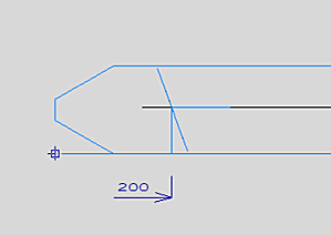
Note: To get the angle lines into the sketch as shown in the picture above, insert two extra NC_PARAMETERS lines into the %ncgnorms%\ncgrobot.ind file. These are the NC_PARAMETERS lines that use the type 912 and $FACEPLATE_TO_PLATE_ANGLE variable. You can find examples in the standard norms.
Note: In some cases when the parts have been numbered using the Auto Number function with the Compare option, a face plate angle may appear mirrored in the profile sketch. To prevent this, add the desired face plate angle keyword to the standard .pap file %ncgnorms%\aracrobot.pap, in the line starting GEN,$CENTER_DISTANCE (this should be the second line from the top).
Example: GEN,$CENTER_DISTANCE,$PLATE_TO_FACEPLATE_ANGLE
Face plate bending information
Bending information for bent face plates describes the curvature of the face plate. Bending information is presented in profile sketches as bending lines. The sketch shows a bending line for each segment of the face plate that needs to be bent. The bending radius, the start and end points of the bending, and the bending side and angle are shown for each bending line.
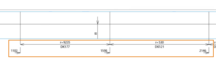
Left: Bending line for the segment between points 1102 and 1598 mm, bending radius 9235, bending on this side ,177 degrees
Right: Bending line for the segment between points 1598 and 2146 mm, bending radius 530, bending on this side, 121 degrees
The bending lines are based on multiple vectors, each defining the bending direction of one short segment of the face plate. By default the system converts by approximation these vectors into one or a few arcs to reduce the number of the bending lines in the sketch. The bending radii are estimations and the results depend on the direction of the face plate. The generated bending information should still be sufficient and accurate enough for the production, and the use of the face plate DXF file is not necessarily needed. Also, there is no need to use a bending template to get the correct bending.
An alternative presentation which is based on the bending vectors without the conversion to arcs, is possible. See Alternative presentation of bending information below.
The following settings in the System Management > Production > Profile Sketch > Face Plates setting group are used to calculate the arcs: Maximum Face Plate Vector Length, Maximum Vector Length Difference, Minimum Face Plate Vector Angle and Maximum Face Plate Radius. It is recommended to keep the default values for these settings.
Note: When a bent face plate is mirrored over the centre line, there can be differences in the bending radii in the profile sketches of the two symmetrical face plates. This is not an error. The system calculates the arcs for the two face plates separately, from the sketch left side to the right side, and the difference in the direction of the source face plate and the mirror face plate may result in slightly different bending radii.
Alternative presentation of bending information
It is possible to make the system use the bending vectors directly, without coverting them to arcs, when it generates the bending lines in the profile sketch. This could result in many bending lines, and may reduce the readability of the sketch. Also, the bending radius and angle are not shown for the bending lines. In this case DXF files and the bending templates are needed in the production.
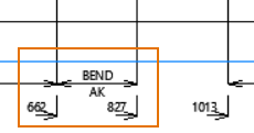
Bending line for the segment between points 662 and 827 mm, bending on other side
To switch to the alternative presentation, change the value of the Face Plate Vector Amplitude setting in System Management > Production > Profile Sketch > Face Plates to zero or less.