Plate calibration symbols
Some grinding machines or edge preparation systems may require specific markings for the grinding start and end points in the plate DXF. These calibration symbols can be included in the part DXFs by enabling Plate Calibration Symbols in the System Management application, Production > Plate Cutting Data > Calibration Symbols.
Also, the Rearrange texts automatically option must be selected for the coding script that is used to code the plate. Coding scripts can be created and modified in System Management > Production > Plate Cutting Data > Coding Scripts.
Examples of symbols that mark the grinding start point (on the left) and grinding end point (on the right):


The start symbol is shaped so that it can point to the end symbol. Based on the pointing shape of the start symbol, the grinding machine can find the end symbol. The system will align the symbols by the longest diagonal between them.
The symbols are user-defined models, which allows using customized, machine-specific symbols.
- The models are stored in the %ncgnorms%\mod2d directory.
- The model used for the start symbol must be named as calibstart.mod.
- The model used for the end symbol must be named as calibend.mod.
Placement of the symbols in the DXF
The symbols are placed along the longest diagonal of the part, inside the part at a certain offset from the outer contour of the part. The offset can be set in the System Management application. See Related settings in the System Management application.
- If the symbol or a part of it falls outside of the outer contour of the part, or inside a hole on the part, after the offset has been applied the system places the symbol to another position along the longest diagonal. The total shift of the symbol is logged in the coding log.
- If the system cannot find an applicable position for a symbol, a "chktxt" warning message is logged in the coding log.
The symbols are placed on the part only if the longest diagonal equals or exceeds the minimum acceptable diagonal length that has been set in the System Management application. See Related settings in the System Management application.
The symbols are placed in their own layer in the DXF. The layer name and the used pen number can be set in the System Management application. See Related settings in the System Management application.
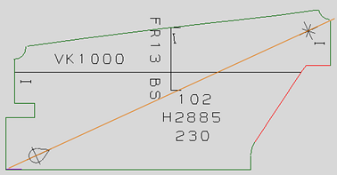
The picture below shows an example on how the symbols can be placed:
Related settings in the System Management application
The following settings in the System Management application, Production > Plate Cutting Data > Calibration Symbols, control the placement of the orientation symbols:
- Plate Calibration Symbols – Specifies if the plate calibration symbols are to be shown on the DXF of the part or not.
- Minimum Diagonal Length – Specifies the minimum length that the longest diagonal must have for the symbols to be placed.
- Offset From Outer Contour – Specifies the offset from the outer contour of the part for the placement of the orientation symbols along the longest diagonal.
For more information, see Calibration Symbols.
The layer name and the used pen number can be set in Production > Plate Cutting Data > DXF Output > Layers Colours 2, Calibration Symbols ID setting.