Creating Enclosed Plates in View
A plate can be created with the Construction > Plates > Insert > Enclosed in View function in the 3D-Contek application by indicating a position in the active view. The plate is created at the indication point and it will be related to the plates in cross section and hull lines surrounding the indication point. The hull line types that are accepted as relations are seams and butts. The system defines the relations automatically. Plates in view are not accepted as relations. The relations must be located in the active (solid) block.
Cutouts and snipes can be added immediately when the plates are created.
Note: Cutouts and snipes will not be inserted between two hull lines.
Do the following:
-
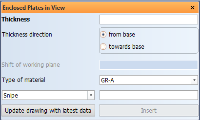
Select Construction > Plates > Insert > Enclosed in View. The Enclosed Plates in View dialog opens.
-
Enter the plate Thickness and define the plate's Thickness direction.
-
Optionally you can shift the reference plane of the plate by defining the Shift of working plane.
-
Select the plate's material type in Type of material.
-
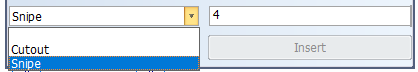
Optionally you can add a cutout or a snipe to the plate by selecting the appropriate option from the drop-down menu. Cutouts and snipes will not be inserted between two hull lines.
-
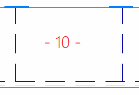
Indicate the centre point for the plate in the graphical window. The system places a thickness indication at the indication point.
The system searches for relations around the indication point in counter-clockwise direction. The exact position of the indication point affects how the system defines the relations, especially when one of the relations is part of a very small part of the desired plate contour. In that case you should indicate closer to this small area. The image below illustrates how the placement of the indication point affects the defining of the relations.
 Show/hide image
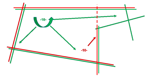
The green indication point results in the green relations, and the red indication point results in the red relations.
-
To create the plate, click Insert. The system briefly highlights the found relations one by one. If the system fails to create the plate, an error message is shown.
The dialog stays open, and you can continue inserting plates one by one.
The view in the graphical window is not updated automatically. To update the view, click Update drawing with latest data.
The thickness indications are only removed when the view is updated, or when the function stopped.
-
Once you have created all the desired plates, close the dialog and stop the function by clicking the cross symbol at the top right corner of the dialog.
Next time when the function is started, the previously used thickness, material type and cutout/snipe information is prefilled/preselected.
Note: Plates in cross section (to be used as a relation) need to cross the view plane including the visibility settings for plates in cross section. The visibility settings for the viewing depth of the drawing area can be changed with the Distance in front of view and the Distance behind view settings in Construction > General > Properties > Visibility.