Pillars in section
The Pillars in Section function can be used for quickly creating a series of pillars under a deck plate without having to switch the view. Pillars can be created horizontally in rows and vertically in columns, or both horizontally and vertically in grid formation. The relations and end types of the pillars are automatically determined by the system.
-
The end types are determined by the rules defined in the autoendtype configuration files, which define the automatic end type assignment for profiles. See Profile end type rules for more information. The end types can later be changed with the Construction > Pillars > Modify > End Type function.
Pillars are created orthogonally even when the view is a slanted view.
Relations
The system automatically searches for and determines the relations. Plates and hull lines in hull group 0 are considered when searching for relation candidates.
-
The system only considers parts from solid and dashed blocks (relative to the current block) when searching for the relation candidates.
-
Relations to straight and bent profiles, profiles as property, shell frames, face plates (girders), and diamond brackets are supported. The system considers these objects as relation candidates, in addition to plates.
-
If there is a face plate (girder) or profile (straight or bent) just under the deck plate, the system uses the face plate or profile as the relation instead of the plate.
-
Plates at an angle of less than or equal to 45 degrees are considered to be a relations to plates in cross-section. At the end of the search, the system checks if the nearest plate in cross-section has profiles (straight or bent) attached to it. Depending on the situation, the pillar may become related to the profile and not the plate.
-
Plates at an angle of more than 45 degrees are skipped (for example, bulkheads under a deck). There is one exception: If such plates have face plates or diamond brackets attached to them, the face plates or diamond brackets are considered as potential relations.
-
Initially the system tries to relate to hull group 0, both above and below the deck plate (relative to the current view). If such relations are possible, their distances are used as the base for a comparison when checking if there are other objects closer to the current view. If there are there are no objects below or above the current view, the system attempts to relate to a hull line in group 0, if possible.
-
If there is no plate in plan view, the system looks for plates above, relative to the current view. If the system finds a plate at an angle of 45 degrees or less, it first checks for profiles (straight or bent) on the plate as potential relations. If there are no profiles, the system looks for face plates (girders), diamond brackets and shell frames as potential relations. For plates at an angle of 45 degrees or more, only face plates and diamond brackets are considered. If none of these object is found, the system attempts to relate to the hull line above.
-
Shell frames from all hull group numbers are considered as potential relations, no just from hull group 0.
The system searches for relation candidates below and above the specified starting coordinates in the view direction. If no suitable objects are found below or above, the system displays an error, and no pillars are created.
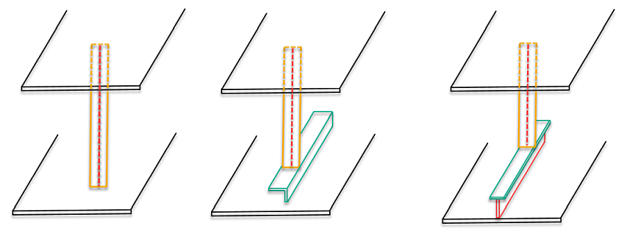
Left to right: Pillar between 2 decks; Pillar related to profile; Pillar to related to face plate on plate in cross-section (girder)
Note: Profiles and pillars do not have topological relations to face plates, therefore auxiliary lines are used as relations.
Creating pillars in section
Do the following:
-
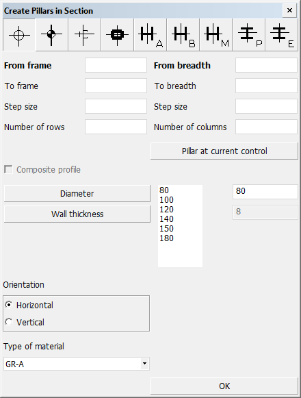
Select Construction > Pillars > Insert > in Section in the 3D-Contek application. The Create Pillars in Section dialog opens.
-
Select the pillar type by clicking a thumbnail image in the top row. Only symmetrical standard pillar types are available. User-defined pillar types are not supported.
-
Define the starting and end positions of the pillars by entering the From and To values in the input boxes. All grid values, with possible offsets, and also fixed values can be used.
Clicking Pillar at current control fills the From values with the current control coordinates. See Snap keys.
-
Enter the horizontal (on the left) and vertical (on the right) Step size. This sets the distance between the pillars. If left empty, the system uses the default which is one grid value.
-
Enter how many pillars to create horizontally and vertically in Number of rows and Number of columns, respectively. If left empty, the system determines the numbers automatically based on the step sizes.
-
Select the dimensions of the pillars. Depending on the pillar type they can be one or more of the following: Diameter, Wall Thickness, Body Size, Width and Profile Size.
-
Select the Orientation of the pillars. The orientation is used to determine the plane of the pillars. The plane affects the end type positions, among other things.
-
Select the Type of material.
-
Click OK to create the pillars.
Example of creating pillars under a deck
The following example demonstrates how to create a series of pillars in a grid formation under a deck plate.
Initial situation
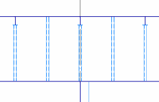
We are in a top view and looking at a deck plate. Underneath the deck plate there are several plates in cross-section, and the plates in cross-section have face plates on them (girders).
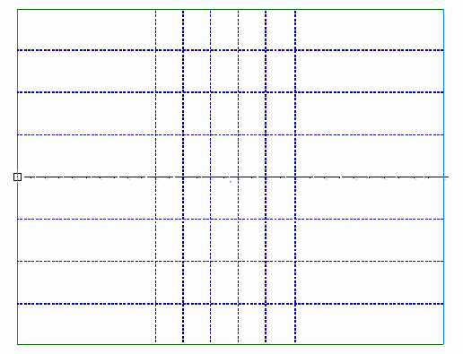
Left: Top view of deck plate in 3D-Contek Right: Initial situation seen in Hull Viewer
We want to create 15 horizontally oriented Pipe type pillars of size 80x8 mm and material GR-A in a 3x5 grid formation:
-
3 rows of pillars at frames 20, 21 and 22
-
5 columns of pillars on sides at height values −2000, −1000, 0, 1000 and 2000
Procedure
To create the pillars, do the following:
-
Select Construction > Pillars > Insert > in Section.
-
In the Create Pillars in Section dialog, use the following values and selections:
-
Select the first pillar type on the left. This type is Pipe.
-
Values From breadth 20, To breadth 22, Step size 1, Number of rows 3.
These values will result in 3 pillars created at consecutive frames, starting at frame 20.
-
Values From height −2000, To height 2000, Step size 1000, Number of columns 5.
These values will result in 5 pillars with a distance of 1000 mm between them, starting from height −2000.
-
Click Diameter and select 80.
-
Click Wall thickness and select 8.
-
In Orientation select Horizontal.
-
In Type of material select GR-A.
-
-
Click OK.
Result
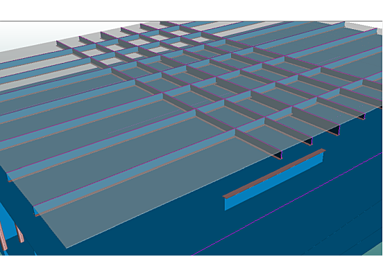
The system creates 15 pillars underneath the face plates (girders), but not all pillars are related to face plates. Two pillars are related directly to the deck plate, at positions where there are no girders (FR21 in length and −1000 and 1000 in breadth). There are girders at FR20 and FR22 in length and at −2000, 0 and 2000 in breadth, and at those positions the pillars are related to the girders.
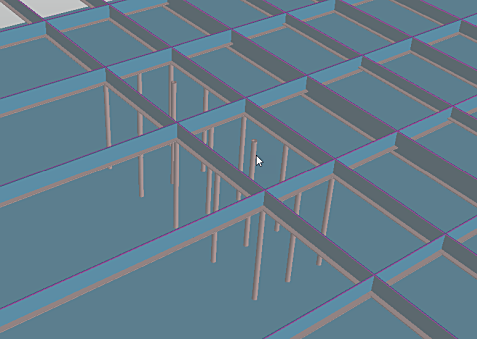
Left: Result in 3D-Contek Right: Result in Hull Viewer