Indicating face plate relations in plan view
The contour of a face plate is defined by indicating the relations that set the starting and end points of the face plate.
Instead of indicating the relations in the graphical window, you can enter fixed values or parallel distances in the Face Plate Relations dialog to define the face plate relations.
Note: If the 1st and 3rd relations are fixed value relations, the 2nd relation is to the main plate, and there are two or more intersection points with the 2nd relation and the 1st and 3rd relations, the relations must be defined in the order that follows the main plate contour direction. See Special case: multiple intersections with plate and fixed value relations for more information.
The available methods for indicating the relations depend on the following:
-
Along how many parts of the plate contour the face plate is to be placed: one or more.
-
The angle between the parts of the plate contour (A,B,C): less than 120 degrees, or 120 degrees or more.
Note: Changes of construction in the surroundings of a plate may increase or decrease an angle beyond the 120 degree limit. This may result in changes in the face plate that is placed on the plate. To avoid this, we recommend to use the 1 vector relation type instead of the Complete relation type when defining the plate relations.
-
Whether there is a curvature on the plate (a rounding radius has been applied to the angle between parts of the plate contour).

The following use cases and their available indicating methods are described below:
- Creating a cace plate on one part of the plate contour
- Creating a face plate on more than one part of the plate contour
- Creating a face plate on a curvature
Note: When you indicate the face plate relations, always click outside of the plate.
Creating a cace plate on one part of the plate contour
Angle less than 120°, no curvature
In case the parts of the plate contour have an angle of less than 120 degrees between them, and there is no curvature where you want to place the face plate, there are two optional methods to define the relations.
-
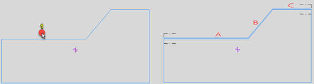
Method 1: Indicate only that part of the plate contour where you want to place the face plate (1/A).
The face plate will end at the point where it meets the next plate contour part, because the angle to the next part is less than 120 degrees.
-
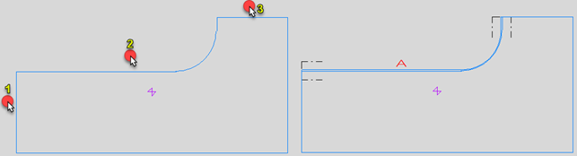
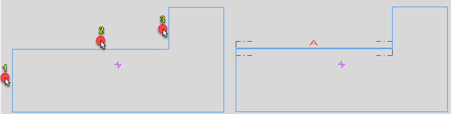
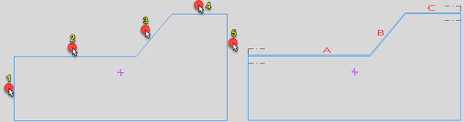
Method 2: Indicate the parts of the plate contour to be used as the limiting relations (1, 2, 3), including the part where you want to place the face plate (2/A). The intersections of the indicated relations will be used as the starting and end points of the face plate. The order of indicating the relations does not matter.
Angle 120° or more, no curvature
In case the parts of the plate contour have an angle of 120 degrees or more between them, and there is no curvature where you want to place the face plate, there are two optional methods to define the relations.
-
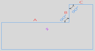
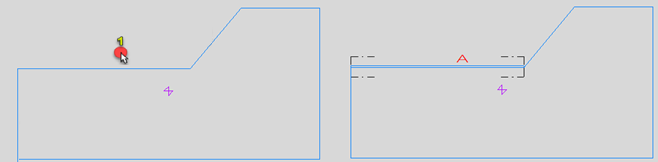
Method 1: Indicate only the part where you want to place the face plate (1/A). Note that you must use the 1 vector relation type for this to work, because there are angles of more than 120 degrees between parts. Using the Complete relation relation type would extend the face plate along to the next parts.
-
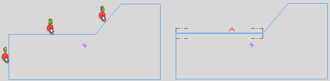
Method 2: Indicate the parts of the plate contour to be used as the limiting relations (1, 2, 3), including the part where you want to place the face plate (2/ A). The intersections of the indicated relations will be used as the starting and end points of the face plate. The order of indicating the relations does not matter.
Creating a face plate on more than one part of the plate contour
Angle less than 120°, no curvature
In case the parts of the plate contour have an angle of less than 120 degrees and there is no curvature where you want to place the face plate, you must indicate all the limiting relations.
-
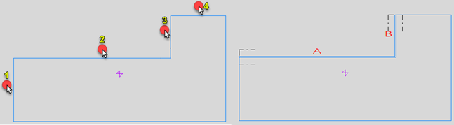
Indicate the parts of the plate contour to be used as the limiting relations (1, 2, 3, 4), including the parts where you want to place the face plate (2/A, 3/B). The intersections of the outermost indicated relations (1, 4) will be used as the starting and end points of the face plate. The order of indicating the relations does not matter.
Angle 120° or more, no curvature
In case the parts of the plate contour have an angle of 120 degrees or more between them, and there is no curvature where you want to place the face plate, there are two optional methods to define the relations.
-
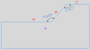
Method 1: Indicate only one of those parts of the plate contour where you want to place the face plate (1/ABC).
The face plate will not end at any point where it meets another plate contour part if the angle between the two parts is more than 120 degrees.
-
Method 2: Indicate the parts of the plate contour to be used as the limiting relations (1, 2, 3, 4, 5), including the parts where you want to place the face plate (2/A, 3/B, 4/C). The intersections of the outermost indicated relations (1, 5) will be used as the starting and end points of the face plate. The order of indicating the relations does not matter.
In this case, because the angles between parts A, B and C are more than 120 degrees, you could also indicate only one of the relations/parts where you want to place the face plate (2/A, 3/B, 4/C) and the outermost relations (1, 5). That is, indicate 1-2-5, 1-3-5, or 1-4-5.
Creating a face plate on a curvature
The angle size rule is not valid for rounded angles, because the whole curvature contour is considered one relation. There are two optional methods to define the face plate relations in this case.
-
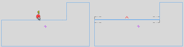
Method 1: Select the curvature by clicking outside of the plate, on the side of the plate where the curvature is (1/A).
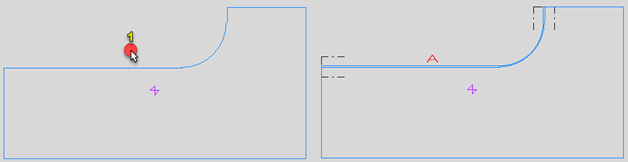
The face plate will start and stop where there is an angle of less than 120 degrees between parts of the plate contour.
-
Method 2: Indicate the parts of the plate contour to be used as the limiting relations (1, 2, 3), including the curvature (2/A). The intersections of the indicated relations will be used as the starting and end points of the face plate. The order of indicating the relations does not matter.