Direction
With this function you can change the body and thickness direction and the molded side placement of profiles. See Molded side placement for profiles for more information on the molded side placement setting.
Do the following:
-
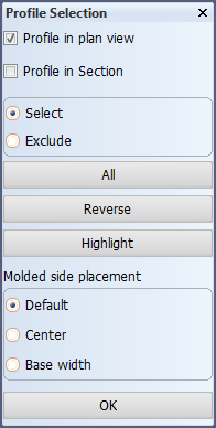
Either Profile in plan view or Profile in Section is preselected in the Profile Selection dialog, depending on what you selected in the menu. This can be changed as desired.
 Show/hide image
Molded side placement selection is not shown when changing direction.
Selection treatment
- Select – Item(s) you indicate are selected.
- Exclude – Exclude items from the current selection.
Selection buttons
- All – Select all items at once.
- Reverse – Reverse the current selection.
- Highlight – Highlight the current selection.
-
Indicate the profile(s) you want to modify in the graphical window, and/or use the selection options in the dialog to select and exclude profiles.
-
Make your direction or molded side placement changes.
-
Click OK to confirm the changes.
Body and thickness direction
You can change the body direction and thickness direction of profiles and shell frames.
Select the profiles and shell frames that you want to modify, and then select Body Direction or Thickness direction.
The selection can contain both profiles and shell frames at the same time.
Thickness direction indication in dimensions
The thickness direction of a profile and shell frame is indicated by a thickness line in the profile and shell frame dimension. The placement of the thickness line is affected by the Molded side placement setting. When the setting is changed, the placement of the thickness line changes accordingly, as follows:
- Default – Thickness line is placed on the thickness side.
- Center – No thickness line is shown.
- Base width – Thickness line is placed on the molded side.
Molded side placement
By default the profile or shell frame is placed by its molded side. The molded side position can be changed for profiles and shell frames. This makes it possible to change how the profile or shell frame is aligned with the construction item that is located on the other side of the plate.
Do the following: Select the profiles and/or shell frame(s), and then set their desired molded side placement. Your selection can contain both profiles and shell frames at the same time.
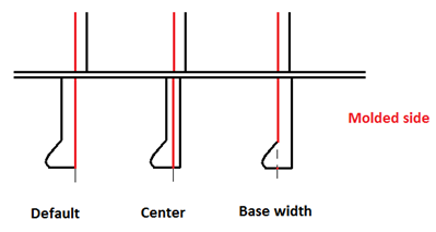
- Default – The profile is placed by its molded side.
- Center – Molded side is placed at the center of the profile or shell frame body. Placement is by the midpoint of the profile or shell frame thickness or width.
- Base width – Molded side is placed on the thickness side. Placement is by the thickness side (at full thickness or width).
The following image demonstrates the options:
Note: Changing the molded side placement is not available for user defined profile types. Molded line is always placed on the molded side (Default setting).
See Molded side placement for profiles and Molded side placement for shell frames for more information.