Molded side placement for profiles
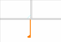
By default a profile is placed by its molded side. It is possible that the profile is not aligned as desired with the construction item that is located on the other side of the plate, if both parts have the default thickness direction. This is because it is the molded lines of the parts that are aligned.
When creating a profile, it is possible to choose its molded side position by selecting the desired Molded side placement setting in the Create Profile dialog. This makes it possible to change how the profile is aligned with the construction item that is located on the other side of the plate.
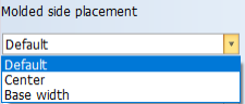
The molded side position can be changed from the default to the midpoint of the profile body, or to the thickness side of the profile. The image below shows the three available options:
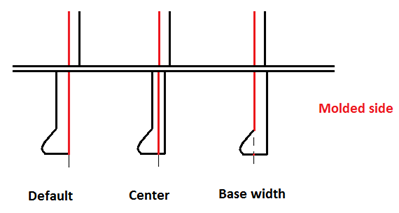
- Default – The profile is placed by its molded side.
- Center – Molded side is placed at the center of the profile body. Placement is by the midpoint of the profile or shell frame thickness or base width.
- Base width – Molded side is placed on the thickness side. Placement by the thickness side (at full thickness or width).
The molded side placement differs for various profile types. In principle, it is the width at the profile base. In case of I-bars and UN-profile the thickness of the profile is used. The table below shows the possible placements when Base width placement is selected. The center shift is always half of the base width shift.
|
Profile type |
Base width |
|
|---|---|---|
|
400 |
Flat bar |
Shift of thickness |
|
401 |
Bulb bar |
Shift of thickness |
|
402 |
Equal angle bar |
Shift of thickness |
|
403 |
Unequal angle bar |
Shift of thickness |
|
405 |
Pipe |
Shift of pipe wall thickness |
|
406 |
Half round |
Shift of half of the width |
|
407 |
Square |
Shift of width |
|
408 |
T-bar |
Shift of thickness |
|
409 |
H-bar (HB) |
Shift of width |
|
410 |
Duct |
Shift of flange size |
|
411 |
Unp profile (UP) |
Shift of flange size |
|
412 |
Corrugation |
N/A |
|
413 |
H-bar (HA) |
Shift of width |
|
414 |
Unp profile (PU) |
Shift of flange size |
|
415 |
I-bar (IP) |
Shift of thickness |
|
416 |
Axis |
Shift of width |
|
417 |
Unp profile (UN) |
Shift of thickness |
|
419 |
H-bar (HEM) |
Shift of width |
|
420 |
I-bar (IE) |
Shift of thickness |
Note: Changing the molded side placement is not available for corrugation profiles and user defined profile types. Molded line is always placed on the molded side (Default setting).
Presentation of profiles with molded side placement
Many profile types in bulb view are presented with a dashed or solid line and end shapes. The end shapes of the profile in bulb view indicate which molded side placement the profile has. For more information on how the system administrator can edit the type files to indicate molded side placement, see Profile end type flags in the Norms Type Files Administrator's Guide.