Cutouts
The cutouts.dat file defines how NAPA Steel parametric shape identifiers for cutouts are converted to CADMATIC Hull cutouts. Lugs for the cutouts can be included if so desired.
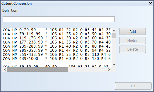
These settings can be made in System Management > Projects > NAPA Steel > Connection Settings > Cutout Conversion.
Syntax for file content:
|
NAPA identifier |
CADMATIC Hull profile type |
profile height range |
profile flange range |
CADMATIC Hull cutout type number |
L-var | value¹ |
R-var |
value¹ |
| ¹ Numerical expressions in NAPA Steel connection settings can be used. | ||||||||
COBA HP 0-79.99 * 100 L1 700 R1 25 R2 15 R3 45 R4 25-15 R5 70 RD 75
COBA HP 80-119.99 * 100 L1 700 R1 25 R2 20 R3 50 R4 25-20 R5 75 RD 75
COBA HP 120-177.99 * 100 L1 700 R1 30 R2 30 R3 60 R4 30-30 R5 85 RD 75
COBA HP 178-239.99 * 100 L1 700 R1 40 R2 40 R3 70 R4 30-40 R5 100 RD 75
COBA HP 240-289.99 * 100 L1 700 R1 55 R2 50 R3 80 R4 35-50 R5 120 RD 75
COBA HP 290-359.99 * 100 R1 65 R2 50 R3 95 R4 40-50 R5 135
COBA HP 360-440.99 * 100 R1 75 R2 50 R3 110 R4 40-50 R5 150
COBA HP 440-1000 * 100 R1 75 R2 50 R3 120 R4 40-50 R5 160
COBA HG 59-79.99 40-40 100 R1 25 R2 15 R3 60 R4 25-15 R5 85
COBA HG 59-79.99 49-60.99 100 R1 25 R2 15 R3 75 R4 25-15 R5 105
COBA HG 79-105.99 49-60.99 100 R1 25 R2 20 R3 75 R4 25-20 R5 105
COBA HG 69-99.99 60-74.99 100 R1 25 R2 15 R3 90 R4 25-15 R5 120
COBA HG 99-139.99 60-74.99 100 R1 35 R2 20 R3 90 R4 25-20 R5 125
COBA HG 74-99.99& 74-84.99 100 R1 25 R2 15 R3 100 R4 25-15 R5 135
COBA HG 99-159.99 74-84.99 100 R1 35 R2 15 R3 100 R4 25-20 R5 135
COBA HG 124-255.99 84-90.99 100 R1 45 R2 20 R3 115 R4 25-20 R5 150
COBA HG 149-255.99 90-105.99 100 R1 50 R2 25 R3 130 R4 25-25 R5 165
COBA HO 59-80.99 40-40 100 R1 25 R2 15 R3 60 R4 25-15 R5 85
COBA HO 59-79.99 49-60.99 100 R1 25 R2 15 R3 75 R4 25-15 R5 105
COBA HO 79-105.99 49-60.99 100 R1 25 R2 20 R3 75 R4 25-20 R5 105
COBA HO 69-99.99 60-74.99 100 R1 25 R2 15 R3 90 R4 25-15 R5 120
COBA HO 99-139.99 60-74.99 100 R1 35 R2 20 R3 90 R4 25-20 R5 125
COBA HO 74-99.99& 74-84.99 100 R1 25 R2 15 R3 100 R4 25-15 R5 135
COBA HO 99-159.99 74-84.99 100 R1 35 R2 15 R3 100 R4 25-20 R5 135
COBA HO 124-255.99 84-90.99 100 R1 45 R2 20 R3 115 R4 25-20 R5 150
COBA HO 149-255.99 90-105.99 100 R1 50 R2 25 R3 130 R4 25-25 R5 165
COBA * * * 100 R1 25 R2 15 R3 45 R4 25-15 R5 75
COAA HG 59-79.99 40-40 100 R1 25 R2 15 R3 60 R4 25-15 R5 85
COAA HG 59-79.99 49-60.99 100 R1 25 R2 15 R3 75 R4 25-15 R5 105
COAA HG 79-105.99 49-60.99 100 R1 25 R2 20 R3 75 R4 25-20 R5 105
COAA HG 69-99.99 60-74.99 100 R1 25 R2 15 R3 90 R4 25-15 R5 120
COAA HG 99-139.99 60-74.99 100 R1 35 R2 20 R3 90 R4 25-20 R5 125
COAA HG 74-99.99& 74-84.99 100 R1 25 R2 15 R3 100 R4 25-15 R5 135
COAA HG 99-159.99 74-84.99 100 R1 35 R2 15 R3 100 R4 25-20 R5 135
COAA HG 124-255.99 84-90.99 100 R1 45 R2 20 R3 115 R4 25-20 R5 150
COAA HG 149-255.99 90-105.99 100 R1 50 R2 25 R3 130 R4 25-25 R5 165
COAA HO 59-80.99 40-40 100 R1 25 R2 15 R3 60 R4 25-15 R5 85
COAA HO 59-79.99 49-60.99 100 R1 25 R2 15 R3 75 R4 25-15 R5 105
COAA HO 79-105.99 49-60.99 100 R1 25 R2 20 R3 75 R4 25-20 R5 105
COAA HO 69-99.99 60-74.99 100 R1 25 R2 15 R3 90 R4 25-15 R5 120
COAA HO 99-139.99 60-74.99 100 R1 35 R2 20 R3 90 R4 25-20 R5 125
COAA HO 74-99.99& 74-84.99 100 R1 25 R2 15 R3 100 R4 25-15 R5 135
COAA HO 99-159.99 74-84.99 100 R1 35 R2 15 R3 100 R4 25-20 R5 135
COAA HO 124-255.99 84-90.99 100 R1 45 R2 20 R3 115 R4 25-20 R5 150
COAA HO 149-255.99 90-105.99 100 R1 50 R2 25 R3 130 R4 25-25 R5 165
COAA * * * 100 R1 25 R2 15 R3 45 R4 25-15 R5 75
COFA * * * 114 R1 3 R2 -2 R3 2
COFA5 ST 0-119.99 * 108 R1 25 R2 15-15 R3 15*15 R4 2
COFA5 ST 120-177.99 * 108 R1 30 R2 20-25 R3 20*20 R4 2
COFA5 ST 178-239.99 * 108 R1 40 R2 30-40 R3 30*30 R4 2
COFA5 ST 240-289.99 * 108 R1 55 R2 40-55 R3 40*40 R4 2
COFA5 ST 290-359.99 * 108 R1 65 R2 50-70 R3 50*50 R4 2
COFA5 ST 360-1000 * 108 R1 75 R2 60-85 R3 60*60 R4 2
COFA5 * * * 108 R1 75 R2 60-85 R3 60*60 R4 2
BA6 HP 100-119.99 * 116 L1 701 R1 26 R2 40 R3 52 R4 3 R5 6 R6 15.5 R9 26 RA 40 RB 52 RC 3 RD 6 RE 15.5
BA6 HP 120-180 * 116 L1 701 R1 30 R2 40 R3 60 R4 3 R5 7.0 R6 19 R9 30 RA 40 RB 60 RC 3 RD 7.0 RE 19
DEFAULT HP 0-79.99 * 105 R1 30 R2 -30 R3 45 R4 25-30
DEFAULT HP 80-119.99 * 105 R1 35 R2 -35 R3 50 R4 25-35
DEFAULT HP 120-177.99 * 105 R1 45 R2 -45 R3 60 R4 30-45
DEFAULT HP 178-239.99 * 105 R1 50 R2 -55 R3 70 R4 30-50
DEFAULT HP 240-289.99 * 105 R1 50 R2 -65 R3 80 R4 35-50
DEFAULT HP 290-359.99 * 105 R1 50 R2 -75 R3 95 R4 40-50
DEFAULT HP 360-440.99 * 105 R1 50 R2 -75 R3 110 R4 40-50
DEFAULT HP 440-1000 * 105 R1 50 R2 -75 R3 120 R4 40-50
DEFAULT HG 0-79.99 0-40.99 105 R1 25 R2 -25 R3 60 R4 25-25
DEFAULT HG 60-105.99 50-60.99 105 R1 25 R2 -30 R3 75 R4 25-25
DEFAULT HG 70-139.99 61-74.99 105 R1 25 R2 -35 R3 90 R4 25-25
DEFAULT HG 75-159.99 75-84.99 105 R1 25 R2 -40 R3 100 R4 25-25
DEFAULT HG 125-255.99 85-90.99 105 R1 25 R2 -45 R3 115 R4 25-25
DEFAULT HG 150-255.99 91-105.99 105 R1 25 R2 -50 R3 130 R4 25-25
DEFAULT HO 0-79.99 0-40.99 105 R1 25 R2 -25 R3 60 R4 25-25
DEFAULT HO 60-105.99 50-60.99 105 R1 25 R2 -30 R3 75 R4 25-25
DEFAULT HO 70-139.99 61-74.99 105 R1 25 R2 -35 R3 90 R4 25-25
DEFAULT HO 75-159.99 75-84.99 105 R1 25 R2 -40 R3 100 R4 25-25
DEFAULT HO 125-255.99 85-90.99 105 R1 25 R2 -45 R3 115 R4 25-25
DEFAULT HO 150-255.99 91-105.99 105 R1 25 R2 -50 R3 130 R4 25-25
DEFAULT * * * 105 R1 30 R2 -30 R3 45 R4 25-30
Description:
A mapping definition is needed for each imported NAPA Steel shape identifier for cutouts to CADMATIC Hull cutout. Mapping for each cutout is defined on its own line, followed by the CADMATIC Hull profile type the cutout is placed around. Next follows the profile height range and the profile flange range. The ranges are expressed as <minimum value>-<maximum value>. If a certain cutout matches the NAPA Steel parametric shape and the profile it is placed around matches the profile type and its height and flange are within the ranges, the cutout is converted according to that line.
| NAPA shape identifier | Mapping | Result |
|---|---|---|
| COA | COA HP 0-79.99 * 106 R1 22 R2 0 R3 44 R4 27-22 | NAPA COA cutout for HP profile of height 0-79.99 is converted to Hull cutout 106 having the dimensions given for the R variables. |
| COI |
COI * * * 114 R1 3 R2 -2 R3 2 | NAPA COI cutout for any profile type is converted to Hull cutout 114. |
| DEFAULT | DEFAULT HG * * 105A | NAPA DEFAULT cutout for HG profile is converted to Hull cutout 105, alternative type A. |
| DEFAULT | DEFAULT HP * * 105 L1 701 R2 5 R3 50 R9 20 RD 85 | NAPA DEFAULT cutout for HP profile is converted to Hull cutout 105 having the dimensions given for the R2 and R3 variables. Lug type 701 is applied on the cutout with the dimensions given for the R9 and RD variables. |
|
The profile height and flange ranges' minimum and maximum values are floating point values. Example: 0-79.99. Wildcard * can be used for the hull profile type, and the profile height and flange ranges (if used, all values match). See the examples above. Numerical expressions with mathematical operators + - * / can be used with the R variable dimensions. Alternative types are supported. See line 3 for an example. Lugs are supported with L variables. See line 4 for an example. |
||
For T-stiffeners converted to a plate with girder, the CADMATIC Hull profile type is set to TW. The cutout for this type has to be a girder cutout. For girder cutouts, the R5 to R8 variables are automatically calculated by the conversion program.
Next follows the CADMATIC Hull cutout type number, (optionally) followed by the R-variables and their values. See Numerical expressions in NAPA Steel connection settings.
Lugs can be included with L variables (optional). Additional R variables R9...RG can be used for lug dimensions.
Example:
A NAPA Steel cutout COA*140*7 placed around a HP104X7.
This will match the following line:
COA HP 119-176.99 * 106 L1 701 R1 30 R2 0 R3 60 R4 35-30 R9 20 RD 85
In CADMATIC Hull this will create a cutout of type 106 with R1 = 30, R2 = 0, R3 = 60 and R4 = 5. Lug type 701 is applied on the cutout with R9 = 20 and RD = 85.
Defining Non-Default Positions for the Height and Flange Parameters
It is possible that for certain profiles the height and flange dimension parameters are located in non-default positions in the mapping. For example the cutout properties of NAPA angle bars differ from those of HP profiles and flat bars so a non-default mapping is needed.
Non-default mapping can be done by using the Hidx and Fidx parameters (profile height index and profile flange index, respectively) which correspond to the dimension parameters in the NAPA cutout profile (cutout ID). The syntax is as follows:
<NapaID> <HullProfName> Hidx <profile_height_index> Fidx <profile_flange_index>
The default mappings, which the system uses if Hidx and Fidx are not defined explicitly, are as follows:
-
If the NAPA cutout has only 2 dimension parameters in its cutout profile, for example COA*100*8¹, then
-
Hidx = 1 (corresponding to 100 here)
-
Fidx = 2 (corresponding to 8 here)
-
-
If the NAPA cutout has 4 dimension parameters in its cutout profile, for example DFLT*0*9*0*90¹, then
-
Hidx = 4 (corresponding to 90 here)
-
Fidx = 2 (corresponding to 9 here)
¹ The * character is a delimiter separating the parameters.
-
These parameters are defined on a separate line for a specific NAPA profile type and Hull profile type combination (<napa shape identifier> <hull bracket main type>). For example, a mapping line COA HO Hidx 1 Fidx 3 means that the 1st parameter in the cutout profile is used for the height, and the 3rd one is used for the flange for mapping the cutouts of all COA HO profiles. The line can be placed anywhere in the mapping file.
Note: You must use either both parameters or neither (using either Hidx or Fidx alone is not allowed).
Below is a valid example for mapping the NAPA COA profile to Hull HO profile.
COA HO Hidx 1 Fidx 3
COA HO 80-99.99 * 105 R1 %1 R2 10
COA HO 100-119.99 * 105 R1 %1 R2 15
COA HO 120-150 * 105 R1 %1 R2 20