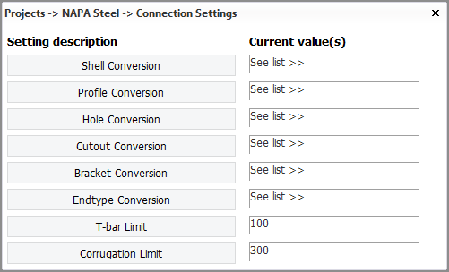
Connection Settings
Projects > NAPA Steel > Connection Settings
With the settings here you define how specific structural entities in the NAPA Steel model are converted to structural entities in the CADMATIC Hull model when using the Tools > NAPA Steel Integration function in the 3D-Contek application.
Settings for each entity are stored in a separate file in the napa_steel subdirectory of the project's norms directory %NCGNORMS%. The files can be edited manually as well. The files can also be reused in other projects. For more information on the files, see Settings in the norms and its subtopics.
For information on the use of numerical values in calculations, see Numerical expressions in NAPA Steel connection settings.
Shell Conversion
Define the mapping of NAPA Steel hull surfaces to CADMATIC hull group numbers.
Mapping for each NAPA Steel hull surface is defined using the following syntax:
<Napa Surface Name> < Hull group number>
These settings are stored in the shell.dat file in %NCGNORMS%\napa_steel. For more information, see Shell.
Profile Conversion
Define how NAPA Steel profile types are converted to CADMATIC Hull profile types. This conversion applies to regular profiles, bent profiles, (bent) pillars, face plates, and shell frames.
It is possible to define a mapping for each NAPA Steel stiffener type to a CADMATIC profile type, including dimensions. Mapping for each profile type is defined on its own line, using the following syntax:
<napa profile identifier> <hull profile type> <dimension index or value>
These settings are stored in the profiles.dat file in %NCGNORMS%\napa_steel.
For more information, see Profiles.
Hole Conversion
Define how NAPA Steel parametric holes are converted to CADMATIC Hull standard holes. This conversion applies to holes in main objects (plates) and holes in stiffeners (profiles).
A mapping definition is needed for each imported NAPA Steel standard hole to CADMATIC hole, including dimensions. Mapping for each hole type is defined on its own line, using the following syntax:
<napa shape identifier> <hull hole type> <dimension index or value>
These settings are stored in the holes.dat file in %NCGNORMS%\napa_steel.
For more information, see Holes.
Cutout Conversion
Define how NAPA Steel parametric shape identifiers for cutouts are converted to CADMATIC Hull cutouts. Lugs for the cutouts can be included if so desired. This conversion applies to cutouts in plates for profiles, and also for cutouts in profiles (standard, arbitrary, and shell frames).
Lugs can be included with L variables (optional). Additional R variables R9...RG can be used for lug dimensions. The syntax is as follows:
<napa shape identifier> <hull profile type> <profile height range min>-<profile height range max> <profile flange range min>-<profile flange range max> <hull cutout main type><hull cutout alternative type> [<L value> <dimension index or value>] [<R value> <dimension index or value>]
For the profile type, profile height range, and profile flange range the * wildcard can be used, which means that all values match.
Non-default mapping for height and flange parameters can be done by using the Hidx and Fidx parameters (profile height index and profile flange index, respectively) which correspond to the dimension parameters in the NAPA Steel cutout profile (cutout ID). The syntax is as follows:
<NapaID> <HullProfName> Hidx <profile_height_index> Fidx <profile_flange_index>
These settings are stored in the cutouts.dat file in %NCGNORMS%\napa_steel.
For more information, see Cutouts.
Bracket Conversion
Define how NAPA Steel parametric brackets are converted to CADMATIC Hull brackets.
A mapping definition is needed for each imported NAPA Steel bracket to CADMATIC bracket, including dimensions. Mapping for each bracket type is defined on its own line using the following syntax:
<napa shape identifier> <hull bracket main type><hull bracket alternative type> [<swap axis>] [<R value> <dimension index or value>]
These settings are stored in the brackets.dat file in %NCGNORMS%\napa_steel.
For more information, see Brackets.
Endtype Conversion
Define how NAPA Steel stiffener endcuts (endcodes) are converted to CADMATIC Hull profile endtypes.
Mapping for each endcut/endcode is defined on two lines, using the following syntax:
<NAPA_CODE> <HULL_CODE_ENDTYPE_1_or_2> [<R_TYPE> <R_VALUE>]
<HULL_CODE_ENDTYPE_3_or_4> [<R_TYPE> <R_VALUE>]
These settings are stored in the endcodes.dat file in %NCGNORMS%\napa_steel.
For more information, see Endcodes.
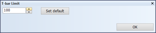
T-Bar Limit
This setting is applicable to profiles and shell frames.
When the size of a T-stiffener in NAPA Steel is larger than the value specified here, the stiffener will be converted to a composite profile. In other cases it will be converted to a regular T-profile.
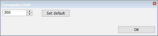
Corrugation Limit
Define how NAPA Steel plate corrugation is converted to CADMATIC Hull plate corrugation.
When the depth of the corrugation is greater than or equal to the corrugation limit value specified here, the NAPA Steel model is imported as a corrugated plate. Otherwise it is imported as a plate with a corrugation profile. The default value for depth is 300 mm.
For more information, see Creating corrugated bulkheads.