Using the Definition tab
As the first step of creating multiple, inter-spaced hull lines, you set the hull line definition in the Insert Multiple Hull Lines dialog, on the Definition tab.
First check out the hull line range subsets which will contain the new hull lines. Then open the Shell application, and load a drawing, or create a new shell view. Then select Construction > Multiple Hull Lines. If there are multiple hull groups visible in your view, the system will prompt you to select one.
The Insert Multiple Hull Lines dialog opens with the Definition tab active.
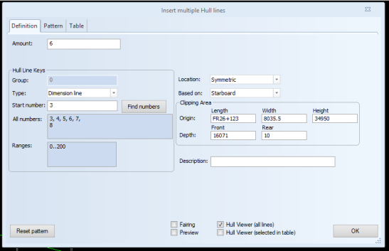
Define the following settings. They will be applied to all of the hull lines to be inserted. When you are done, click OK to save the settings.
Amount – Enter the number of hull lines to create.
Group – Shows the hull group number.
Type – Set the type of hull line to either seam, butt, or dimension line. Seams and butts always appear as solid lines and are always visible. Dimension lines become visible after they have been activated with the Home > General > Show Hull Lines function.
Start number – Set the number of the first hull line. Each time the hull line type is changed, a default value for the number is recomputed. The default value is the first available valid number found for the hull line. If you change this, Find numbers will reset the number to the default. The number must meet the following requirements to be valid:
- It must be unique within the hull group and hull line type.
- It must be between 0.00 and 99999.99.
- It can have a maximum of two decimals.
- It has to be within the ranges of the subset that has been checked out.
The numbers following the first hull line number are calculated in the following way:
If the first number is a whole number, the steps between the following numbers will be 1. Example: In case the start number is 200, the following numbers would be 201, 202, 203, and so on.
If the first number is a decimal number, the steps between the following numbers will equal to the decimal of the first number. Example: In case the start number is 200.25, the following numbers will be 200.50, 200.75, 201.00, 201.25, and so on.
Note: The hull line numbers can be changed after the pattern has been defined. However, this can cause the pattern to become invalid in cases when the user has selected line relations to the hull lines with the replaced numbers (first order circular dependencies). In this case the system displays an error message, and the pattern remains invalid until either the amount, the starting number, or the conflicting relations are changed.
Ranges – Shows the range(s) of hull line numbers available for the current user. Ranges are shown for each selected hull line type. Hull Line Ranges can be set in System Management > Projects > Hull Line Ranges.
Location – Sets the hull lines to appear on starboard, port side or both.
Based on – Set the hull lines to be based on either starboard or port side, if the lines cross the center line. The default value is Starboard. Changing this value is relevant when the hull lines are fully or partially drawn on port side. A hull line can be drawn across the centre line. However for computing the final line, only the starboard or the port side of the line can be used. This setting essentially determines which side that will be.
Clipping Area – These settings define the geometrical space where the hull line is evaluated (the specify a smaller section of the shell view). This space is defined by an origin point with three coordinates and two depth values. The clipping area is therefore limited in depth direction, and unlimited in the other two dimensions (i.e., in length or height in side views).
Once you have defined the hull lines, switch to the Pattern tab, where you can draw the hull lines. See Using the Pattern tab.
Visualizing hull lines
The following visualization functions are available in all of the tabs of the Insert Multiple Hull Lines dialog:
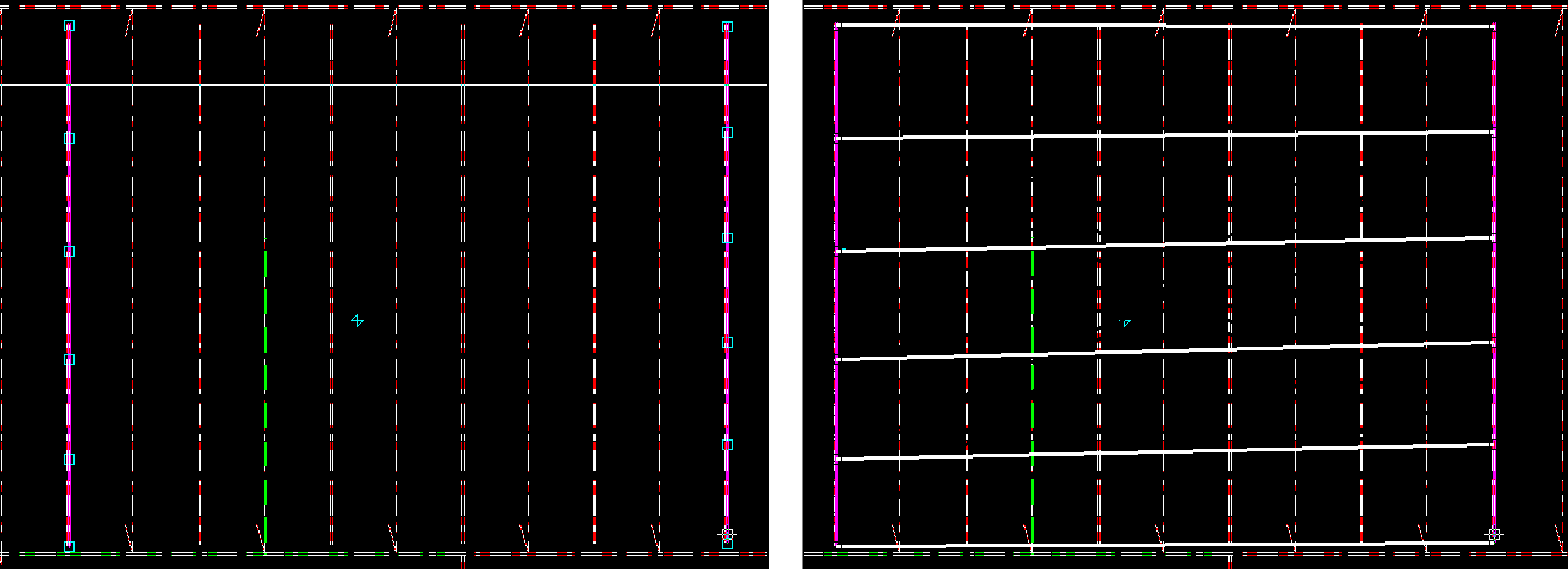
Show the fairing between the points.
The system shows how the faired hull lines look like in the current view. The visualization of the fairing is done by using this function instead of automatic refreshing to avoid unnecessary computations. Also, when visualizing the fairing, not all of the data is recalculated for performance reasons.
- If a side pattern is not valid, fairing will fail.
- If some points are not valid, these points are drawn at (0,0).
The image below shows the same set of hull lines; on the left the fairing option is deactivated, on the right the fairing option is activated.
Show a preview of the final 3D hull lines.
All hull lines and relations are re-evaluated. The system displays all hull lines that have been successfully evaluated. The lines that failed the evaluation are displayed in the error message window.
Show all the hull lines in Hull Viewer.
The hull lines that will be created are displayed in Hull Viewer. If you change the hull lines in the dialog, the displayed hull lines in Hull Viewer disappear. Apply this function again to see the changes you made in Hull Viewer.
If a final hull line cannot be evaluated, only the surfaces appear in Hull Viewer.
When this function is selected, all lines and/or surfaces are displayed,
Hull Viewer (selected in table)
Show those hull lines in Hull Viewer that are selected in the Table tab of the Insert Multiple Hull Lines dialog.
The hull lines that will be created are displayed in Hull Viewer. If you change the hull lines in the dialog, the displayed hull lines in Hull Viewer disappear. Apply this function again to see the changes you made in Hull Viewer.
If a final hull line cannot be evaluated, only the surfaces appear in Hull Viewer.