Adjusting values in the table
You can choose the amount of data displayed in the table by activating and inactivating the last four buttons of the toolbar. All options can be enabled simultaneously and in any combination. By default, angle to shape values are shown when the user enters the tab for the first time.
The table displays points on the hull line.
The information in the cell are displayed in the following order:
interspace, (HLP grid coordinate1, HLP grid coordinate2), B: angle to base, S: angle to grid
Values that can be displayed in the table
Show/ Hide Interspaces
 Interspace is the 3D distance between the hull line in the selected row and the hull line in the next row of the same column. The bottom row of the table, that displays the last hull line is always blank (-).
The interspace is calculated in cell [i,j] the following way:
- The system computes the intersection point P1 between the polyline of the grid coordinate on column 'j' and the polyline of the hull line of row 'i'.
- The system computes the intersection point P2 between the polyline of the grid coordinate on column 'j' and the hull line of row 'i'+1.
- The interspace [i,j] is the distance between P1 and P2 along the polyline of the column grid coordinate:
interspace [i'j] = distance (P1,P2)along polyline_j
 This button displays the coordinates of the intersection of the hull line in the selected row and column. If evaluation of the intersection fails, the displayed value is (error, error).
Values with Angles
The Show angle to base and Show angle to shape options help you to add intersection plane properties to the hull lines. Consider the following important information about the angle values:
- Angle values are always in the range [0, 180) degrees.
- If the incoming angle is different than the outgoing, both values are displayed.
- Angles are always calculated around the real intersection point of the line and the column relation. This means, that if an inserted point is shifted, the most recent intersection point is calculated for the purpose of angle computation.
- If errors are encountered during computation, the value error is displayed.
- If an angle is indeterminable, the value undefined is displayed. (This can happen in cases when the extruded surface is parallel to width-height plane.)
- On the starboard side, angles are calculated by starting from the base or shape tangent and moving clockwise towards the (projected) extrusion direction. The normals of the planes - that define the clockwise direction - depend only on the orientation of the plane:
- for X-Y (using Height grid axis) it is top-toward-bottom
- for X-Z (using Width grid axis) it is starboard-toward-port
- for Y-Z (using Length grid axis) it is aft-toward-fore
- On port side, angles are calculated the same way but a counter-clockwise.
 This option shows the angle deviation between extrusion direction and width axis; calculation is done on the plane defined by the grid coordinate chosen in the columns pattern definition.
 The Angle to shape option shows the angle deviation between extrusion direction and tangent of shape; calculation is done on the plane defined by the grid coordinate chosen in the columns pattern definition.
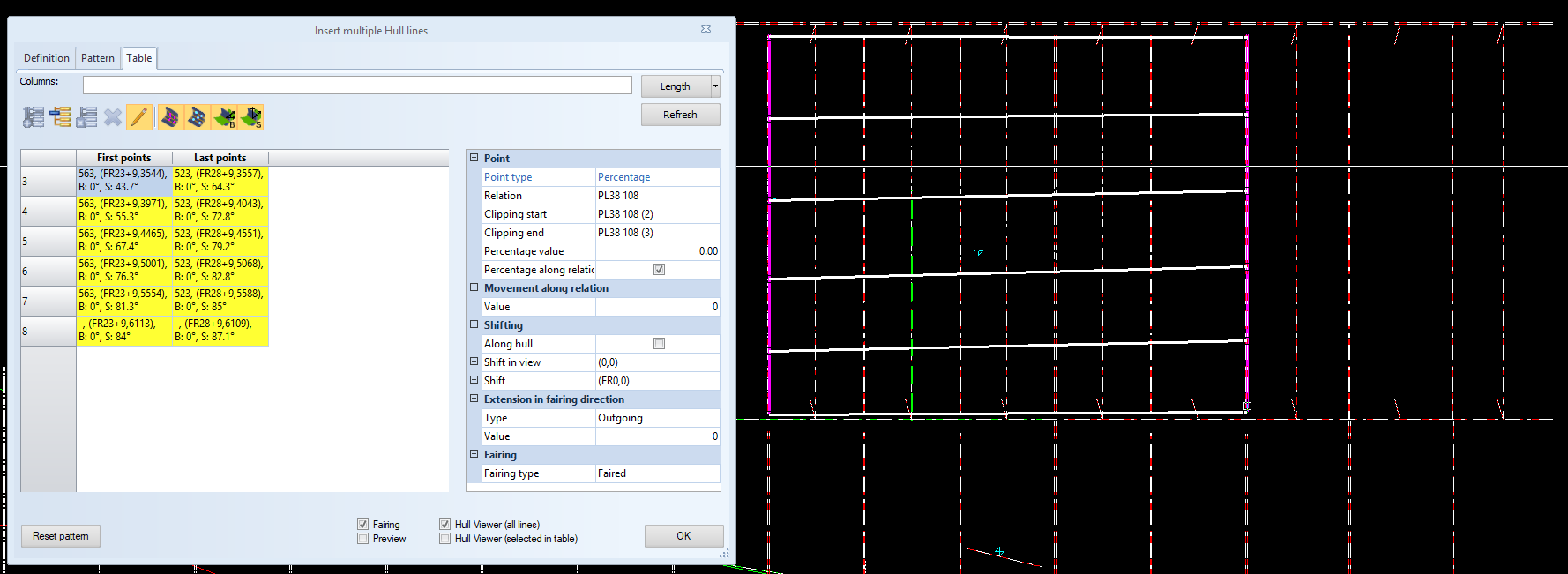
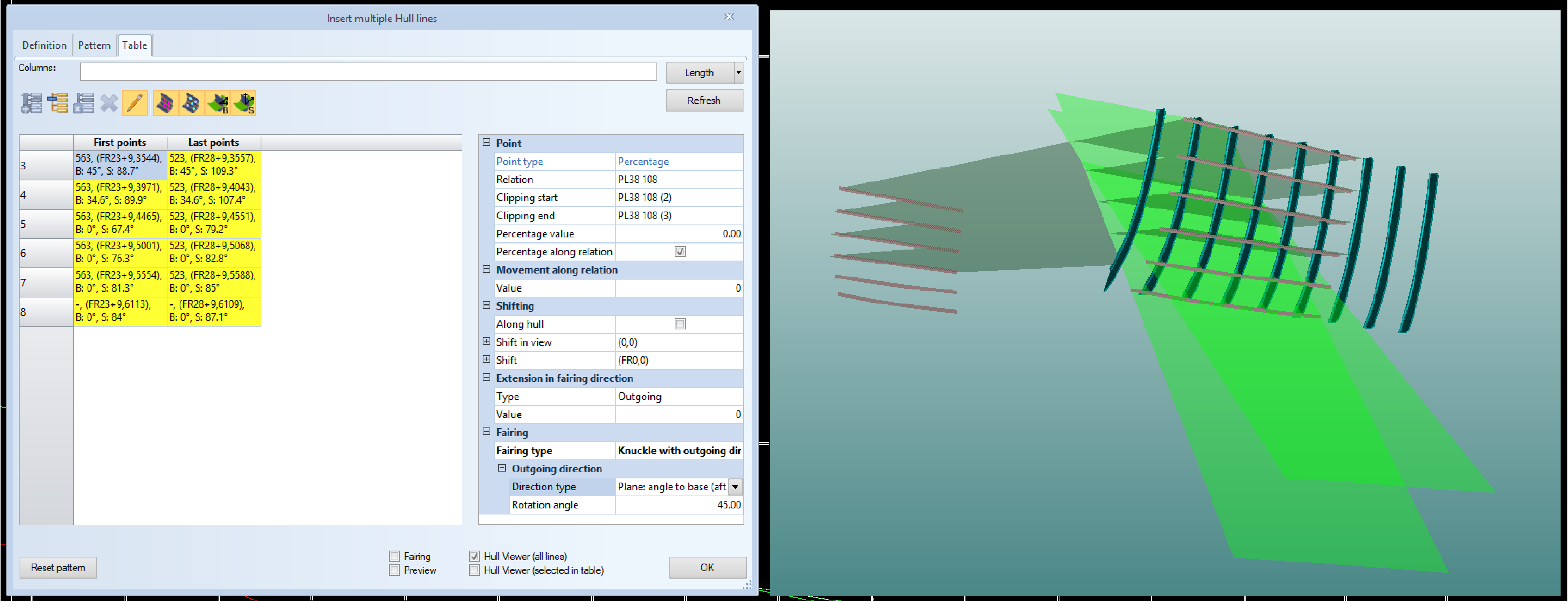
Property grid
A property grid, similar to the one used in the single hull line dialog, is provided along the table to allow the user to customize the inserted points.
To help save working space for the table itself, the grid is not visible at all times. You can display the property grid by using the Show properties option on the toolbar.
The image below shows an example where the angle to base plane properties of a hull line are adjusted in the property grid. The image also shows how the adjusted planes look like in Hull Viewer.
This grid allows users to edit all point properties, including points in intersection planes. You can also select multiple points at the same time. In this case the property grid will display all common attributes and set attributes on all points at the same time. Whenever properties are modified in the grid the table values and preview points are updated.
see Refining line definitions for more information on how to adjust the cells in the table.