Shell plates in cross section
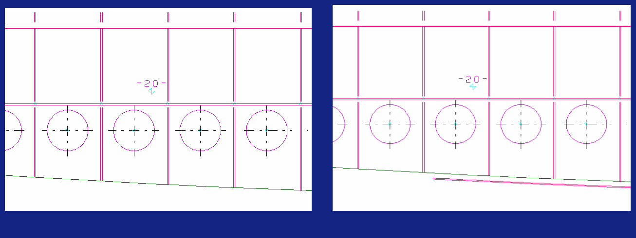
The option to display shell plates in cross section is available in any view created in 2D-Contek, 3D-Contek, HiLTop and Production Information applications. The image below to the left shows a view that does not show intersecting shell plates. The image below to the right shows the same view, but here the intersecting shell plate is displayed.
Shell plates in cross-section can be used as topological relations when creating regular plates.
Shell plates can be presented in the view if they meet the following two conditions:
- The minmax values of the shell plate must be at least partly within the actual drawing area.
- The minimum distance of the shell plate is less or equal to the visibility settings for plates in cross section.
Properties of shell plates in cross section
The shell plates in cross section are presented with the same pen line, dashed line and hatch as the inner plates.
What makes a shell plates in cross section different from regular plates, is that it's only presented with a face or hatch, if its thickness is equal or larger than the following values:
• the thickness value of the shell plate's material type (defined in Logistics > Material Properties in the System Management application) or
• the general visibility setting for maximum plate thickness for lines (defined in Presentation > Visibility > Max. Plate Thickness for Lines in the System Management application).
The system uses the lowest value of these two settings to define how the shell plate in cross section is presented.
In cases when the shell plate only intersects the visibility plane behind or in front of the view plane, the points of the intersection are projected to the actual plane and this resulting line is presented by the system.
Show shell plates in cross section
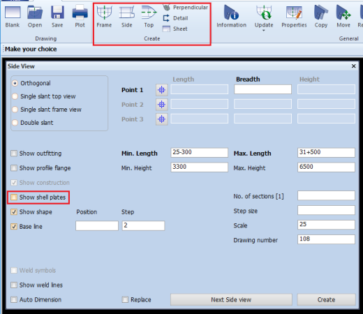
You can display the shell plates in cross section by activating the Show shell plates option in the dialog box. You can activate this option during the following actions:
Creating views
When creating a frame view, a side view, a top view or a perpendicular view, the property Show shell plates can be enabled in the pop up window to include shell plates in the view. When starting the Create view function, this property is disabled by default.
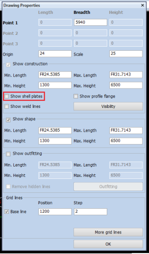
Drawing Properties
The property Show shell plates can be enabled or disabled to include or exclude shell plates in the active view.
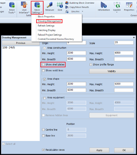
Drawing Management
The property Show shell plates can be enabled or disabled to include or exclude shell plates in all selected views.
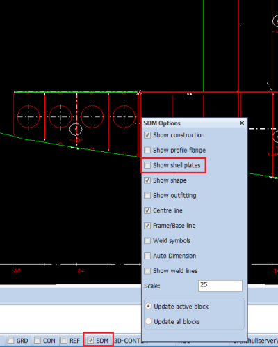
Steel Design Mode
Property Show shell plates is available as part of the default properties to create a view in Steel Design Mode (with toggle SDM enabled).
Isometric view
Shell plates are also visible in the isometric view of a block in the Shell application.