Creating standard holes in Shell
Holes in shell plates can be created as standard holes with the Fixed Hole function in the Shell application. Holes are created in the same way as they are created in inner construction with the 3D-Contek application.
Note: Standard holes cannot be created in perpendicular shell views.
Creating standard holes
Several standard holes can be created in one go.
Do the following:
-
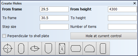
In the Shell application, select Construction > Holes > Fixed. The Create Holes dialog opens (side view is the current view in this case).
-
Define the position of the hole center by entering values in the From fields. The directions depend on the current orthogonal view. Once you have defined the center point, the current control moves to that position.
Enter values in the To fields to create more than one hole. These values set the center position of the furthermost hole. If the second To field is left empty, the value in the second From field is used.
- Step size – Enter the desired distance between the holes. In case of frames, the default value of 1 (frame) is used if the field is left empty.
- Number of items – Enter the number of holes you want to create. If left empty, the system determines the number automatically based on the step size.
With the values in the image above, the system will use 4300 as the To height value, 1 as the step size, and 2 will be the number of holes created.
Perpendicular to shell plate – When selected, the hole projection will always be perpendicular to the shell plate. Otherwise the hole is projected in the view direction it was created or last turned. The projection can be changed later with the Modify > Turn/Shift function.
Click Hole at current control – Use the current control position as the hole center position. See Snap keys.
The system automatically selects the shell plate where the hole is placed based on the hole center point. The hole is placed in the closest shell plate that is perpendicular to the view direction.
-
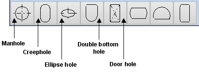
Select the hole type.
-
In the Hole type dialog that opens, enter the dimensions (diameter, width, length, radius, small radius) and other properties (rotation, door type) of the hole. These depend on the type of the hole.
-
Click OK in the Hole type dialog to create the hole(s).
Note: The hole contour can cross the shell plate contour. The exceeding part does not influence the adjacent shell plate.