Create Iceframes
- Adding Text
- Create Shell Frames
- Create Arbitrary Profiles
- Modify Profile Relations
- Retrieve Line Information
- Turn Profiles
- Measure Distance
- Replace Views
You will create a series of ice frames, located between frame 22.5 and frame 30.5. These ice frames can be found on the second example sheet. With exception of ice frames at frame 22.5 and 23.5, all ice frames are supported by a flat bar at the lower end. You will create these flat bars as well.
In order to create these ice frames with supporting flat bars, you will perform the following actions:
- Create nine additional frame views "Frame 22.5" up to "Frame 30.5";
- Create first ice frame HP 200 x 9 within frame view "Frame 23.5";
- Create second and third ice frame by copying the first ice frame to frame views "Frame 22.5" and "Frame 24.5";
- Create the supporting flat bar ST 150 x 10 of the third ice frame within top view "Deck 3500";
- Copy the third ice frame and supporting flat bar to frame views "Frame 25.5" up to "Frame 30.5".
Now, the supporting flat bars ST 150 x 10 will still be in a vertical position instead of alongside the ice frames HP 200 x 9. To achieve that the flat bars are positioned alongside the ice frames, you have to manually turn them to have them placed into the desired position.
This correction must be carried out for each ice frame in its corresponding frame view and consists of two steps:
- Ask the system for the angle at the lower end of the ice frame;
- Turn the flat bar into its correct position alongside of the ice frame.
Overview of actions:
- Create nine frame views "Frame 22.5" until "Frame 30.5"
- Open drawing frame view "108-23d5"
- Choose Do not update
- Place standard text "Frame 23.5" above view with Position set to Interactive
- Create first ice frame HP 200 x 9
- Place hole symbol
- Dimension the ice frame
- Create 2nd and 3rd ice frame by copying the 1st ice frame to frame views "Frame 22.5" and "Frame 24.5"
- Create two welding holes with radius 35 mm
- Open drawing top view "108-3500"
- Choose Update active block
- Create supporting flat bar ST 150 x 10 of the third ice frame
- Copy ice frame with the supporting flat bar to frame 25.5 until frame 30.5
- Correct the relations of the flat bar at frame 30.5
- Open drawing frame view "108-24d5"
- Choose Update active block
- Place standard text "Frame 24.5" above view
- Place hole symbol
- Dimension the shell frame
- Create two welding holes with radius 35 mm
- Determine the angle at the lower end of the first ice frame
- Turn the flat bar to its correct position along the first ice frame
- Repeat these steps for frame 25.5
- Open drawing frame view "108-26d5"
- Choose Update active block
- Place standard text "Frame 26.5" above view
- Place hole symbol
- Dimension the shell frame
- Create one welding hole with radius 35 mm at the upper seam
- Correct the position of the flat bar
- Measure distance for the length of the new lower end type
- Change the lower end type of the ice frame to 'ZJ'
- Repeat these steps for frames 27.5 until frame 30.5
- Open drawing frame view "108-22d5"
- Choose Update active block
- Place standard text "Frame 22.5" above view
- Place hole symbol
- Change the lower end type of the ice frame to 'P'
- Dimension the ice frame
- Create two welding holes with radius 35 mm
- Replace views by means of Drawing Management
- Open drawing frame view "108-22d5" to check the result
Additional description of actions:
- Create nine frame views "Frame 22.5" up to "Frame 30.5"
Select the icon Frame View in the Create section of the Home tab:
![]()
Let's give these views around the same size as the previous frame views, so we can make them smaller later on in this step:
|
Name of panel |
Option |
Value |
|---|---|---|
|
Frame View |
'Length' |
22.5 |
|
|
'Min. Height' |
1500 |
|
|
'Max. Height' |
6500 |
|
|
'Min. Breadth' |
-500 |
|
|
'Max. Breadth' |
|
|
|
'No. of sections' |
9 |
|
|
'Step size' |
1 |
|
|
'Centre line' |
on |
|
|
'Base line' |
off |
|
|
'Height line' |
off |
Note: These intermediate views will be named "108-23d5", "108-24d5", etc.
- Place hole symbol
In top deck 6600 above base a hole is present, which you can recognize by the coloured circle around the midpoint of the hole. You can mark this hole by placing a hole symbol:
![]()
Click the icon Hole Symbol in the Modify section of the Holes ribbon tab and proceed by indicating the aforementioned circle to place the symbol.
- Open drawing frame view "108-24d5"
For slanting parts and parts not situated at a frame station, it's not possible to load the corresponding views by selecting the concerning parts. So selecting the ice frame at frame 24.5 in order to load the frame view "108-24d5" will not work. In such situations, you have to indicate a point in an empty area after which you can select a certain view to be loaded, from the list in the panel Open drawing.
- Change the lower end type of the ice frame to 'ZJ'
Change the lower end type of the ice frame to type 'ZJ' and use the following values:
|
Name of panel |
Option |
Value |
|---|---|---|
|
End type |
'Radius' |
35 |
|
|
'Length' |
135 |
|
|
'Height' |
35 |
Note that the value of 135 is the value you measured in the previous action.
- Change the lower end type of the ice frame to 'P'
Change the lower end type of the ice frame to type 'P' and use the following values:
|
Name of panel |
Option |
Value |
|---|---|---|
|
End type |
'Angle of bevelled edge' |
39 |
|
|
'Nose height' |
71 |
|
|
'Radius' |
50 |
Adding Text
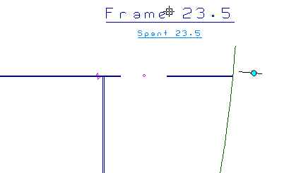
You will now place standard text "Frame 23.5" in a different position than you have done for the other frame views. This because later on in the tutorial you will change the drawing area to a smaller size.
Please click the Text button in the Text section on the Draw ribbon tab:
![]()
The panel Text appears:
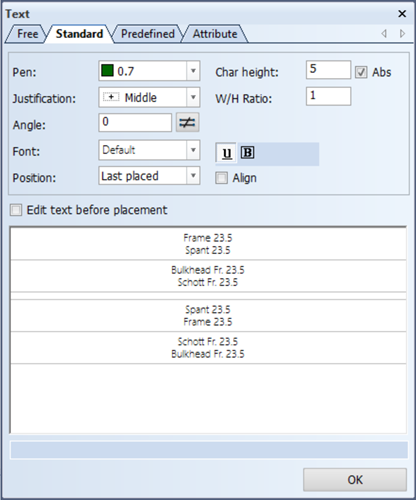
To place standard text in a position different from the last used position, you have to set the value for Position to Interactive and by means of the mouse you can indicate the new position where you would like to have the text be placed.
Proceed to place the standard text as below:
Create Shell Frames
You will create the first ice frame HP 200 x 9 at frame 23.5 by using the Profiles in View option.
Let's create ice frame HP 200 x 9 by selecting the icon Profiles on the Construction tab:
![]()
Now select the first icon Profiles in View in the Insert section of the Profiles tab:
![]()
According to the hint Indicate the hull line/plate you select the hull line by indicating a point to the left side of the hull line. You specify the type of profile and its directions by means of panel Create Shell Frame:
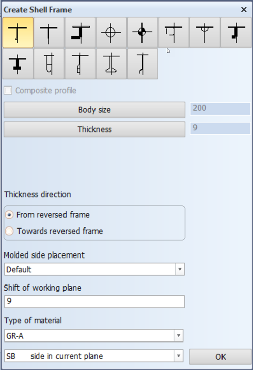
After clicking the OK button, you specify the first and second limitations of this shell frame.
The first limitation will be the lower deck "Deck 3500". So indicate a point just above the lower deck and enter value 0 for the parallel distance from the lower deck:

Select as first end shape the type 'C' and accept the default value '35' for the radius within panel End type by clicking the OK button.
The second limitation will be the upper deck "Deck 6200". So indicate a point just below the upper deck and enter value 0 for the parallel distance from the upper deck:
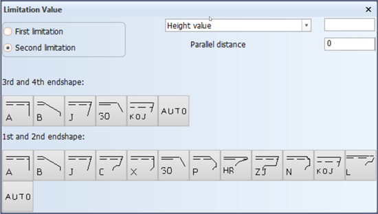
Select for the second end shape the type 'C' with the same radius of 35 mm. After clicking the OK button, the specified shell frame will be created.
Create Arbitrary Profiles
You will create the supporting flat bar ST 150 x 10 of the third ice frame HP 200 x 9 at frame 24.5 by using the Arbitrary Profiles option.
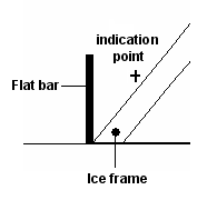
The supporting flat bar ST 150 x 10 will be created between the start point P⊃1; and the endpoint P⊃2; within top view "Deck 3500". The exact position of these points are given in the next figure:
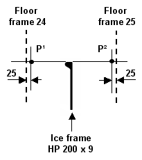
The start point P⊃1; will be defined as an intersection point between the relations:
- A distance parallel to the floor at frame 24 of 25 mm;
- A distance parallel to the top of the ice frame HP 200 x 9 of 0 mm.
The endpoint P⊃2; will also be defined as an intersection point between the relations:
- A distance parallel to the floor at frame 25 of 25 mm;
- A distance parallel to the top of the ice frame HP 200 x 9 of 0 mm.
Both the first and second end shapes of this stiffener will be of type 'B' with an angle of 60 mm and a nose height of 25 mm.
Let's create this flat bar according to the specified position by selecting the icon Arbitrary Profiles in the Insert section of the Profiles tab:
![]()
![]()
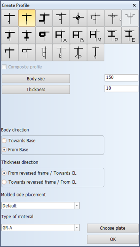
You specify the type of profile and its directions by means of panel Create Profile:
After clicking the OK button, you have to specify the start and endpoint of the profile as well as the end shapes.
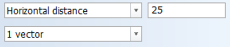
As basis for the start point of the profile, you will define the two relations:
- The horizontal distance to the floor at frame 24, being 25 mm. You define the first relation by indicating a point in front (to the right) of the floor at frame 24 and entering the value 25 for Horizontal distance within panel Profile on plate ? TDB 108:
- The horizontal distance to the top of the ice frame, being 0 mm.
Confirm the definition of this relation by clicking the Accept button.
You define the second relation by indicating the top of the ice frame HP 200 x 9:
Enter the value 0 for Vertical distance within panel Profile on plate ? TDB 108:
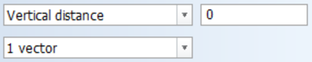
Confirm the definition of this relation clicking the Accept button.
These two relations are presented as additional lines in the graphical screen intersecting each other:
The intersection point of the two lines will determine the start point of the profile.
Now select type 'B' as first end shape:
![]()
The default values for the Angle of edge and Nose height within panel End type are correct. By clicking the OK button you have completely defined the start point of the profile.
As basis for the endpoint of the profile, you will define the two relations:
- The horizontal distance to the floor at frame 25, being 25 mm;
- The horizontal distance to the top of the ice frame, being 0 mm.
You define these relations and the second end shape, which will be of type 'B' with the same default properties, in a similar way as you have done for the start point.
After completely defining both points, the supporting flat bar of the ice frame will be created between the specified points:
Modify Profile Relations
When you take a look at supporting flat bar ST 150 x 10 at frame view 30.5, you will see that due to the copy action, the profile relations of this flat bar are a little messed up. This has to do with the relations of the original flat bar, which is defined between two transverse bulkheads. But because there is no bulkhead located at frame 31, you will need to relate the flat bar to the edge of deck plate "Deck 3500" instead.
Let's modify the flat bar's profile relations by selecting the icon Profile Relations in the Modify section of the Profiles tab:
![]()
After you indicate the flat bar, its profile relations are revealed in the graphical screen by square boxes with numbers in them.
Right click somewhere in a blank area of the graphical screen, and the following menu will pop up:
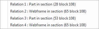
You will need to edit relation number 3, so please proceed by selecting Relation 3: Part in section 27 tdb 108. The relation will light up and the panel Profile Relations becomes active:
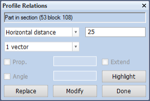
Start by clicking the Replace button to have the system clear out all previous info pertaining relation 3 and proceed by indicating the boundary of the plate. The flat bar will have a parallel distance of 25 mm from the edge of the deck plate "Deck 3500".
Select 'Horizontal distance' and enter 25 mm within panel Profile Relations. Click Modify to confirm the new relation. Now you can edit more of the flat bar's relations if you so choose. In this case none of the other relations need to be edited, so please click Done to close the Profile Relations panel and witness your changes on screen.
Retrieve Line Information
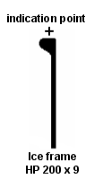
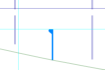
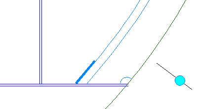
The position of the supporting flat bar ST 150 x 10 is currently vertical:
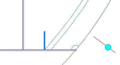
To position this flat bar along the ice frame, you need to turn it around a specified angle. Therefore you will find out the angle at the lower end of the ice frame by retrieving information about this ice frame.
Let's retrieve the angle at the end of the ice frame by selecting the icon Line/Arc Information in the Information section of the Draw tab:
![]()
According to the hint Indicate a line you select the line of the ice frame as illustrated below:
After indicating this line, the system displays panel Line Information with the information about the selected line:
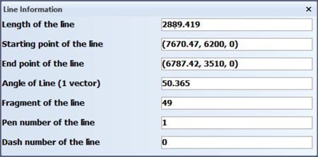
The angle at the lower end of the ice frame will be nearly equal to the angle of the selected line. This angle is rounded off to 50° and consequently the flat bar must be turned 40°.
Turn Profiles
You will turn the flat bar ST 150 x 10 to its correct position along the ice frame HP 200 x 9. Within the current frame view "108-24d5" the flat bar needs to be turned 40°.
Now rotate the profile by selecting the icon Rotate in the Modify section of the Profiles tab:
![]()
By means of panel Profile Selection, you select the flat bar by using the 'Clump' selection method:
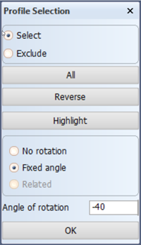
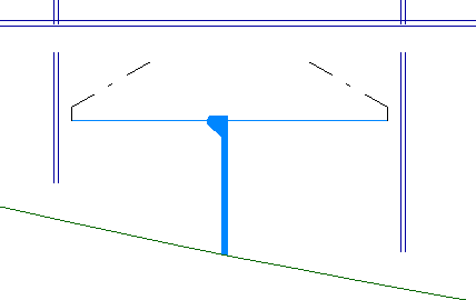
After selecting the flat bar, you enter -40 for Angle. In this case you give a negative value for the angle, because the direction of rotation is clockwise.
Click the OK button and the flat bar will be positioned along the ice frame:
Measure Distance
The ice frames at frame 27.5 until frame 30.5 have an extended draining hole similar to the bulkheads at frames 26 and 27. The way in which to apply them onto the ice frames is done by changing their lower end shape to type 'ZJ'.
But before you do so, you need to measure the distance needed for the draining hole to reach the seam in the hull. This distance is different for each ice frame, so you will need to measure them individually.
Now select the icon Measure Distance in the Information section of the Draw tab:
![]()
Proceed to indicate the start and ending points in the graphical screen alongside the hull, from the deck to where the extended draining hole will stop, as seen in the picture:
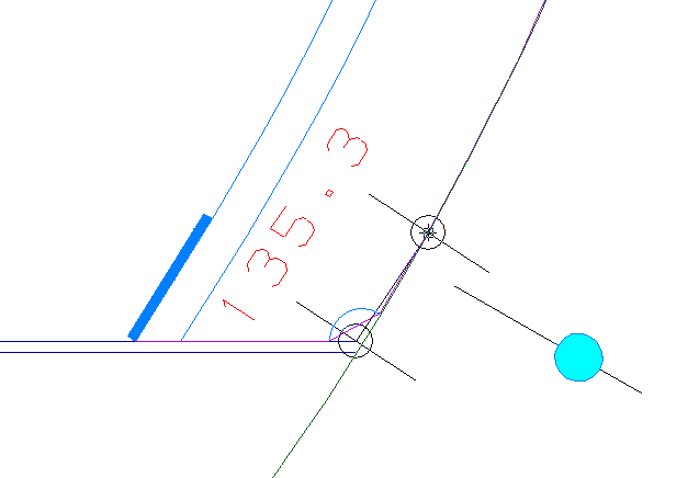
You will see the distance in between these points appear in panel Measure Distance:
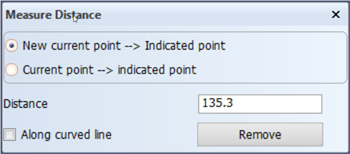
For easy reference we will round off this number to "135". This is the value that you will need to specify when changing the lower end shape of the profile to type 'ZJ'.
Replace Views
Because the ice frames cover only a small part of your view, it is not necessary to have the entire area of the view visible. Therefore you are going to update the area values for these views. This can be done in one action by using the Drawing Management function.
Select the Tools tab and click the arrow under icon More Settings in the Settings section and choose Drawing Management:
![]()
![]()
Now the Drawing Management panel appears. Proceed to select each drawing you wish to update by clicking on them, and they will appear in the Selected list:
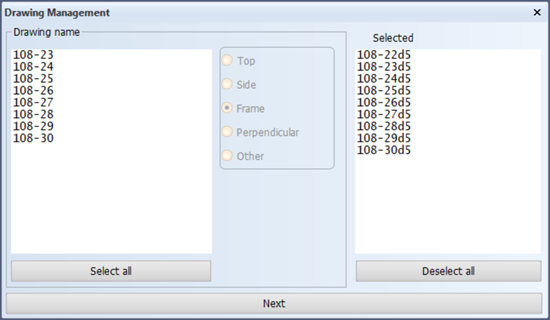
Confirm by clicking the Next button. Let's now make these views as small as possible by using the following values for the listed options:
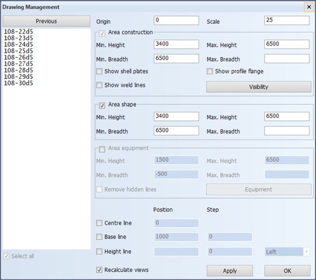
The centre line and the base line can be de-selected because you don't need them in these views.
Click the OK button to confirm your changes. The panel that follows appears only when you have activated the Recalculate views option on the previous panel. This is necessary to update the existing views after you have changed their area definitions.
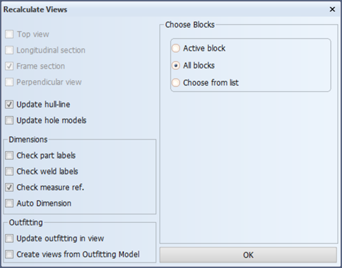
Before recalculation, the existing drawings currently show construction in the active block as well as in the neighbouring blocks. Because the construction of block 102 falls outside of the new area you just specified, you must update 102 as well in order to see its construction disappear from the drawings. This means that all the blocks must be updated and not just the active block.
And lastly, please make sure the hull line is updated as well. Click the OK button to start the recalculation process.
Note: All the 2D items that you have placed in these views will remain exactly where you have placed them.