Create Shell Frames
So far you have seen how to create profiles in orthogonal directions, for example when they run parallel to lines such as waterlines, verticals or frame lines. It is also possible to create a shell frame that runs along a longitudinal line that is not orthogonal, for instance a knuckle line or a seam line. This can be done with use of the application 3D Show.
To learn how to do this, you will create a shell frame along a seam line in 3D Show, after which you will modify the angle of the shell frame in 3D Contek.
And you will also create a bracket in section and modify its angle.
Overview of actions:
- Switch to 3D Show and create a shell frame
- Open frame 30 and rotate the shell frame
- Create arbitrary profile
- Create bracket in section
End situation – Create Shell Frames
Additional description of actions:
- Create arbitrary profile
Creating this arbitrary profile is done in a similar way as creating supporting flat bar ST 150 x 10 .
|
Name of panel |
Option |
Value |
|---|---|---|
|
Profile on plate |
Selected profile type |
|
|
|
'Body size' |
100 |
|
|
'Thickness' |
10 |
|
|
'Body direction' |
Towards reversed frame |
|
|
'Thickness direction' |
Towards base |
|
|
'<1>' |
Indicate left profile HP 120x8 |
|
|
'Parallel distance' |
40 |
|
|
'<2>' |
Fixed height: 3000 |
|
End type |
'1st end shape' |
|
|
|
'Angle of edge' |
60 |
|
|
'Nose height' |
25 |
|
|
'<3>' |
Indicate right profile HP 120x8 |
|
|
'Parallel distance' |
40 |
|
|
'<4>' |
Fixed height: 3000 |
|
|
'2nd end shape'
|
|
|
End type |
'Angle of edge' |
60 |
|
|
'Nose height' |
25 |
Create Shell Frame
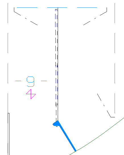
In this exercise you are going to use the 3D Show application to create a shell frame along a dimension line.
Switch to "3D Show" and retrieve block 108. Proceed to select the icon Show Hull Lines in the General section:
![]()
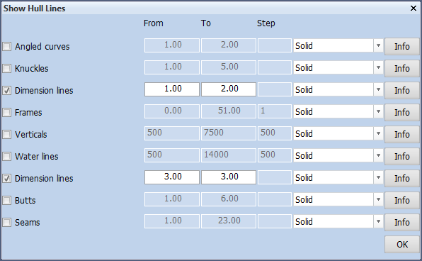
There are two separate rows for Dimension Lines. The difference between them is that the first displays all dimension lines present in the shape database, while the second displays all dimension lines created in the Shell application of CADMATIC Hull. Activate both rows and click OK.
Now all the known dimension lines are displayed in the graphical screen. When you use the 3D-Item Information function, you can find out the identification number of each dimension line. Remember dimension line number 3.
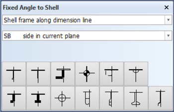
Create the shell frame by selecting on the Construction tab the arrow under icon Shell Frames in the Insert section and choose Fixed Angle to Shell:
![]()
![]()
Now choose Shell frame along dimension line in the panel that appears:
The shell frame will be a bulb profile HP 220 x 10. After choosing its profile type, you can specify the body size and thickness in the next panel that appears, as well as the identification number of the dimension line:
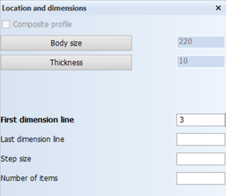
You can leave the rest of this panel unchanged. Click the OK button to proceed to the next panel. In this panel you are given the ability to either indicate a construction part or specify a fixed length.
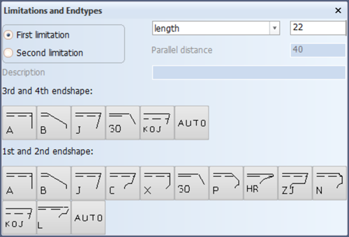
You are going to specify frame 22 as a fixed length for the first limitation with a parallel distance of 40 and then proceed to choose endshape 'A'. For the second limitation, specify frame 31 with a parallel distance of 40 and also the endshape 'A'.
Keep in mind though that when you choose to specify a fixed length, that the shell frame will not be topological to any other construction part in the section.
Turn Shell Frame
Let's switch back to 3D Contek. You will be prompted to save your drawing right before you make the switch. The drawing in 3D Show does not need to be saved.
Open drawing Frame 30, update it and zoom in on the shell frame you created in the previous action.
Modify the shell frame by selecting on the Construction tab the icon Shell Frames, followed by the icon Angles in the Modify section of the Shell Frames tab:
![]()
![]()
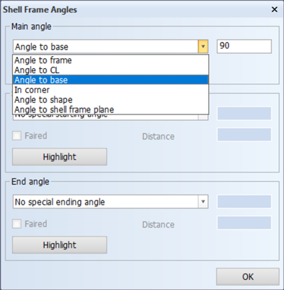
Proceed to indicate the shell frame and click OK. In the panel that appears, change the main angle to Angle to base:
After confirming with OK, the shell frame will be positioned as shown in the detail below:
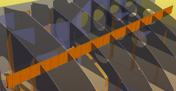
The shell frame has an angle that is 90° to the baseline
Please repeat this action to place the shell frame back in its original position. When in its original position, it will be 90° to the shape of the hull at any given point along the hull. This means that the angle to the baseline will measure a different value at each frame. The shell frame is now not only a bent profile, but a twisted profile as well.
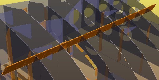
The shell frame has an angle that is 90° to the shape of the hull
Create Brackets in Section
Before you create the bracket in section, you will first draw a 2D line segment to aid you in determining the angle of the bracket that you are about to place.
Start the function Line Segments function on the Draw tab:
![]()
Draw a line segment using the upper right corner of the shell frame for the starting point, and for the ending point snap perpendicular to the arbitrary profile using hot key <p>.
Now create the bracket by first clicking the icon Brackets in Section on the Brackets tab, followed by the icon Type 768:
![]()
![]()
Proceed to draw a selection box around both the shell frame and the arbitrary profile in the panel Select profile(s). After that, click the button Indicate Angle (Line) and then indicate the 2D line segment.
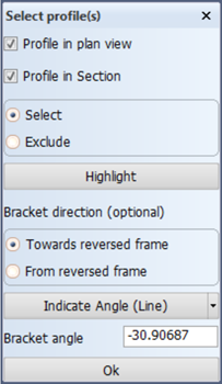
The bracket angle is calculated and automatically displayed. Click OK to proceed to the panel Bracket type 768. Everything is already filled in, so you only have to click OK again. Finally you are asked to select a cornerhole type, and the radius is 25.
The result of the created bracket is as illustrated below: